background image


Electrical power supply:

 120V/60Hz 1 Ph.   

 MOUNTING:  

Adjustable flange is standard.


P250 

P265 

Maximum Input 

250,000 Btu/hr (73 kW) 

200,000 Btu/hr (59 kW) 

Minimum Input 

15,000 Btu/hr (4.4 kW) 

15,000 Btu/hr (4.4 kW) 

Turndown 

5:1 

5:1 

Fuels 

Natural & L.P. Gas 

Natural & L.P. Gas 

Maximum Inlet 

Pressure 

14” w.c. Natural 

14” w.c. LP 

14” w.c. Natural 

14” w.c. LP 

Minimum Inlet 

Pressure 

5.5” w.c. Natural 

11” w.c. LP 

5.5” w.c. Natural 

11” w.c. LP 

WAYNE COMBUSTION SYSTEMS 

801 GLASGOW AVE. 

FORT WAYNE, IN 46803 


PHONE: (260) 425-9200 

(855) WAYNECS 

(800) 443-4625 

FAX: (260) 424-0904 

www.waynecombustion.com 
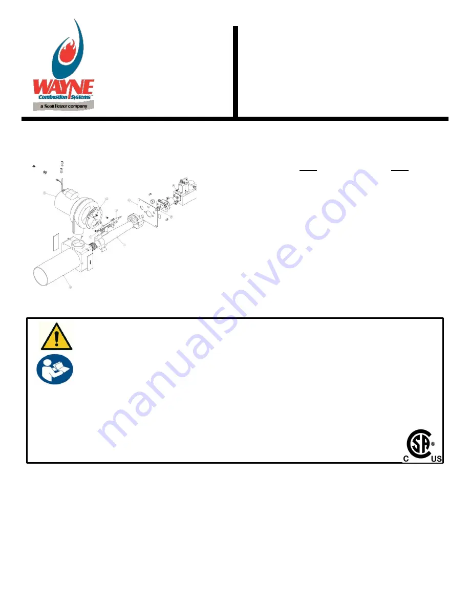
 

iHEAT SYSTEM 

Manual 64659-001| Revision A | Publication Date: 07/06/18 

NOTE: Dimensions in () are informational only. English values take priority. 


READ THIS MANUAL BEFORE USING THIS PRODUCT. FAILURE TO FOLLOW THE INSTRUCTIONS AND SAFETY 
PRECAUTIONS IN THIS MANUAL CAN RESULT IN SERIOUS INJURY OR DEATH. KEEP THIS MANUAL FOR FUTURE 
REFERENCE. INSTALLER: LEAVE THIS MANUAL WITH THE END USER. 
 
INSTALLATION OF THE BURNER MUST BE DONE BY A QUALIFIED INSTALLER IN ACCORDANCE WITH REGULATIONS 
OF THE NATIONAL FUEL GAS CODE ANSI Z223.1/NFPA54, AND IN COMPLETE ACCORDANCE WITH ALL LOCAL 
CODES AND AUTHORITIES HAVING JURISDICTION. 
 
A QUALIFIED INSTALLER IS THE PERSON WHO IS RESPONSIBLE FOR THE INSTALLATION AND ADJUSTMENT OF THE 
EQUIPMENT AND WHO IS LICENSED TO INSTALL GAS-BURNING EQUIPMENT IN ACCORDANCE WITH ALL CODES 
AND ORDINANCES. 


CSA CERTIFICATE NUMBER: 1156769


Summary of Contents for P250 series

Page 1: ...ication Date 07 06 18 NOTE Dimensions in are informational only English values take priority READ THIS MANUAL BEFORE USING THIS PRODUCT FAILURE TO FOLLOW THE INSTRUCTIONS AND SAFETY PRECAUTIONS IN THIS MANUAL CAN RESULT IN SERIOUS INJURY OR DEATH KEEP THIS MANUAL FOR FUTURE REFERENCE INSTALLER LEAVE THIS MANUAL WITH THE END USER INSTALLATION OF THE BURNER MUST BE DONE BY A QUALIFIED INSTALLER IN A...

Page 2: ... c CO2 O2 CO PPM INSTALLER S NAME CONTRACTOR NAME CONTRACTOR ADDRESS CONTRACTOR PHONE NUMBER CONTRACTOR LICENSE DATE OF INSTALLATION COMMENTS ABOUT INSTALLATION START UP THESE INSTRUCTIONS SHOULD BE AFFIXED TO THE BURNER OR ADJACENT TO THE APPLIANCE BURNER APPLIANCE SERVICE LOG SERVICE DATE TECHNICIAN COMPANY ADDRESS CONTRACTOR LICENSE WORK PERFORMED ...

Page 3: ...ge that appears next to the warning describes the hazard which can be either written or pictorially presented NEVER remove or tamper with the warning labels safety devices or guards fitted on the unit Wayne Combustion System is NOT responsible for any bodily injury and or property damage that may result from operation outside of the stated operating conditions for which this unit was intended Indi...

Page 4: ...MOXOXIDE IS A COLORLESS ODORLESS GAS THAT CAN KILL FOLLOW THESE RULES TO CONTROL CARBON MONOXIDE Do not use this burner if in an unvented enclosed area Carbon monoxide may accumulate Do not adjust the pressure regulator High pressures produce carbon monoxide Check flue gases for carbon monoxide This check requires specialized equipment Allow only qualified burner service persons to adjust the burn...

Page 5: ...mber when calling or writing Proposition 65 material This product can expose you to chemicals including lead nickel carbon monoxide and sulfur dioxide which are known to the State of California to cause cancer or birth defects or other reproductive harm For more information go to www p65Warnings ca gov If any instructions in the manual are not clear contact Wayne Combustion Systems at 1 260 425 92...

Page 6: ... the Burner 8 Sizing and Inspection of Gas Piping 10 ELECTRICAL WIRING OF BURNER 13 SETUP 14 Orifice 14 Calibrating the Blower 16 Dip Switches 17 Modulating Valve 17 Final Steps of Setup 19 SEQUENCE OF OPERATION 20 iHEAT BOARD FEATURES 20 On Off Feature 20 Diagnostic Lights 21 TROUBLESHOOTING GUIDE 22 SERVICE INFORMATION 24 Electrode Position Factory Setting 25 Wiring Diagram 27 Exploded Views 28 ...

Page 7: ... accessed through an opening on the face of the iHEAT control See setup information for the proper settings of the switches The control also incorporates a series of lights that signify the operating state of the system and assist in the diagnosis of the system should it require repair In the event of improper combustion air blower speed the control will act to shut off the flow of gas by de energ...

Page 8: ...HEAT are also available with all burner parts contained in an enclosure Such burners have additional mounting holes on the enclosure body or may be mounted on an optional pedestal Figure 1 Mounting Flange Dimensions Flange may not support the full weight of burners that have an attached enclosure Use the mounting holes provided in the enclosure or the optional pedestal accessory for additional sup...

Page 9: ...59 001 REV A 07 06 18 9 An alternate flange with a smaller profile is used on some models per OEM specifications The dimensions for the alternate flange are shown below Figure 2 Alternate Flange Dimensions ...

Page 10: ...ng the gas supply pressure to the burner A manual shutoff valve shall be installed in the gas supply line external to the appliance See Figure 3 The piping should be so installed as to be durable substantial and gas tight It should be clear and free from cutting burrs and defects in structure or threading Aluminum tubing should not be used for the main gas supply Joint compounds pipe dope should b...

Page 11: ... any pressure testing of the gas supply piping system at test pressures equal to or less than 1 2 psig 3500 PaG Pipe Sizing Chart for Natural Gas 0 0 5 psi with Straight Schedule 40 Metal Pipe This table is based on 0 0 5 psi inlet pressure specific gravity of 0 6 and a pressure loss of 0 5 w c Maximum Capacity of Pipe Size in Btu per Hour Length of Pipe ft 1 2 3 4 1 1 1 4 1 1 2 10 175 000 360 000...

Page 12: ... 000 5 501 000 125 74 000 155 000 292 000 600 000 899 000 1 730 000 4 876 000 150 67 000 140 000 265 000 543 000 814 000 1 568 000 4 418 000 200 58 000 120 000 227 000 465 000 697 000 1 342 000 3 781 000 250 51 000 107 000 201 000 412 000 618 000 1 189 000 3 351 000 300 46 000 97 000 182 000 373 000 560 000 1 078 000 3 036 000 350 42 000 89 000 167 000 344 000 515 000 991 000 2 793 000 400 40 000 ...

Page 13: ...as leaks use a soap solution After the piping and meter have been checked completely purge the system of air Be sure to relight all the gas pilots on other appliances ELECTRICAL WIRING OF BURNER Electrical components for the burner are mounted on a subplate which ships with the burner The wiring diagram in Figure 13 shows how to wire the burner to the subplate and where to connect line voltage The...

Page 14: ...g low fire rate with this orifice would be 10 000 Btu hr Selecting the proper gas orifice size is important for optimal system performance If the selected orifice produces a high fire rate that is more than necessary for the appliance during loaded operation the iHEAT system will operate at the very low end of the firing rate a majority of the time The best system performance will be obtained when...

Page 15: ...0 1250 2 00 140 000 5 13 64 0 2055 1 75 140 000 30 0 1285 2 50 150 000 4 0 2090 2 00 150 000 29 0 1360 2 75 160 000 3 0 2130 2 50 160 000 28 9 64 0 1405 2 75 170 000 1 0 2280 2 75 170 000 27 0 1440 3 00 175 000 A 0 2340 2 75 175 000 26 0 1470 3 00 185 000 B 0 2380 3 00 185 000 25 0 1500 3 25 190 000 C 0 2420 3 00 190 000 24 0 1520 3 25 200 000 E 1 4 0 2500 3 25 200 000 22 5 32 0 1570 3 50 210 000 ...

Page 16: ...ait for LEDs on the iHEAT board to go out Position the dip switches on the iHEAT board such that dip switch 8 is on and all others are off Turn on power to the burner system The iHEAT control is now in a calibration mode During this calibration process the lights on the control board will illuminate in the following manner FLASH flash T INPUT off VALVE off BLOWER on 24V CAL flash The calibration p...

Page 17: ... to the control board and gas be connected to the valve Use a manometer to measure the outlet pressure Set the high pressure setting before the low pressure setting The valve must be mounted with the modulating coil horizontal The gas valve controls the pressure of the gas supplied to the burner in order to adjust the burner s firing rate The gas valve will not be able to supply enough gas to achi...

Page 18: ... the recommended manifold gas pressure setting based on table at right Locate the 8mm high pressure adjustment nut This is the larger nut located on the valve coil Set the appliance to call for full fire After the burner ignites turn the high pressure nut counterclockwise until the outlet gas pressure is below the desired outlet gas pressure setting then turn clockwise until desired pressure is ac...

Page 19: ... manometer hoses and tighten the pressure tap screws where the hoses were Final Steps of Setup Turn off power to the burner system and wait for all lights on the iHEAT board to go off Set the dip switches on the board in the proper positions for normal operation according to the table given in the Dip Switches section Run the appliance at full fire for ten minutes and then check the burner exhaust...

Page 20: ... points the iHEAT system incorporates an on off feature When the iHEAT system has modulated down to the minimum heat input but the set temperature is not maintained the iHEAT system will turn the burner off This will be indicated by the Valve light as it will flash during the burner off cycle When the appliance temperature reduces a few degrees below the temperature set point the iHEAT will bring ...

Page 21: ... board s on off feature has turned the valve off The valve contacts will open when an abnormal condition is sensed combustion air blower RPM out of spec either the line voltage or the 24 volt inputs to the iHEAT control are absent the iHEAT control is in calibration mode or the thermostat signal is absent upon start up Blower The Blower light illuminates when the combustion blower is operating pro...

Page 22: ...rner switch on check for 24 volts across 24Vac terminals repair if necessary Flash Flash Off or Flash Off On 1 Indicates signal from t stat is absent or not in proper range Check wiring connections at COM and 0 24V or 4 20mA terminals 2 Check t stat for proper output Flash On Off or Flash Flash On 1 Check wiring connections at MOTOR L and MOTOR N terminals 2 Check wiring connections at the three T...

Page 23: ...for proper connection of black rectifier plug on gas valve 5 Verify gas flow during ignition trial If gas flows but ignition does not occur correct ignition problem If gas does not flow during ignition trial diagnose problem with gas valve Appliance runs temperature well over t stat set point will not control appliance temperature Flash On On On On 1 Check wiring connections at 4 20 mA and COM ter...

Page 24: ...ze for desired firing rate and type of gas 2 Check high pressure setting of modulating gas valve adjust as necessary Appliance runs temperature cycling above and below t stat set point by approximately 5o F Flash On On or Flash On On 1 This is normal operation for iHEAT control with V53 and later software A flashing Valve light indicates the burner has been turned off to maintain appliance tempera...

Page 25: ...64659 001 REV A 07 06 18 25 Electrode Position Factory Setting 1 4 1 16 6 4 1 6 mm 1 8 3 2 mm gap Figure 11 P250 Electrode Positions Factory Setting ...

Page 26: ...64659 001 REV A 07 06 18 26 Figure 12 P265 Electrode Positions Factory Setting 1 8 3 2 mm gap 5 16 1 16 6 4 1 6 mm ...

Page 27: ...64659 001 REV A 07 06 18 27 Wiring Diagram Figure 13 Wiring Diagram ...

Page 28: ...M W STUDS MACH 1 5 62715 003 TUBE HOUS 9 1 6 62371 033 ORIFICE 1 7 62049 002 PLATE BACK HOUSING P250 265 1 10 64503 001 MOTOR BLOWER 1 12 63566 001 SHUTTER AIR ASM PIE STYLE 1 18 62556 002 BRACKET ELECTRODE MOUNT DI 1 19 63916 001 WIRE IGNITOR LEAD 5MM 27 L 1 20 62411 080 WIRE SENSOR 24 BLUE 1 32 64050 006 GAS TRAIN GAS AIR MOD 1 34 21756 011 FLANGE ASM ADJ BLACK 1 36 100428 002 GASKET FLANGE STD ...

Page 29: ...TRODE MOUNT DI 1 4 62715 001 TUBE HOUS 5 1 6 63256 002 PLATE BACK HOUSING P250 265 1 7 61828 ORIFICE 1 9 64503 001 MOTOR BLOWER 1 11 63566 001 SHUTTER AIR ASM PIE STYLE 1 17 21756 011 FLANGE ASM ADJ BLACK 1 19 63916 001 WIRE IGNITOR LEAD 5MM 27 L 1 20 62411 080 WIRE SENSOR 24 BLUE 1 29 64050 006 GAS TRAIN GAS AIR MOD 1 33 100428 002 GASKET FLANGE STD 4 ID 1 Figure 15 Exploded View of P265 Burner ...

Page 30: ...re 16 Mounting Plate View PARTS LIST ITEM PART NUMBER DESCRIPTION QTY 1 64528 001 CONTROL IGN WAYNE 0 PREPURGE 1 2 64054 006 IHEAT CONTROL BOARD GAS AIR 1 3 60186 004 TRANSFORMER 120V 24V 30VA 1 4 63592 003 TERMINAL BLOCK 3 POLE LC 2 ...

Page 31: ...S WAYNE warrants to those who purchase its Oil Burner Models for resale or for incorporation into a product of resale that its burner is free from defects in material and workmanship under normal use and service for thirty six 36 months from the date of manufacture ALL GAS BURNERS manufactured by WAYNE will be similarly warranted for eighteen 18 months from date of manufacture except where origina...

Page 32: ...64659 001 REV A 07 06 18 32 NOTES ...

Reviews: