background image

RP/IS-F-FZ-765 

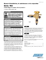
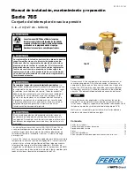
Installation, Maintenance, and Repair Manual 

Series 765 

Pressure Vacuum Breaker Assembly 

1/2" – 2" 

Read this Manual BEFORE using this equipment. 
Failure to read and follow all safety and use information 

can result in death, serious personal injury, property 

damage, or damage to the equipment. 
Keep this Manual for future reference. 

Local building or plumbing codes may require modifications to 

the information provided. You are required to consult the local 

building and plumbing codes prior to installation. If the 

information provided here is not consistent with local building 

or plumbing codes, the local codes should be followed. 

This product must be installed by a licensed contractor in 

accordance with local codes and ordinances. 

Need for Periodic Inspection/Maintenance:

  This product 

must be tested periodically in compliance with local codes, but 

at least once per year or more as service conditions warrant. 

All products must be retested once maintenance has been 

performed. Corrosive water conditions and/or unauthorized 

adjustments or repair could render the product ineffective for the 

service intended. Regular checking and cleaning of the product’s 

internal and external components helps assure maximum life and 

proper product function. 

Freeze sensor solely provides alerts about a possible freeze event 

and cannot prevent a freeze event from occurring. User action is 

required to prevent freeze conditions from causing product and/ 

or property damage. 

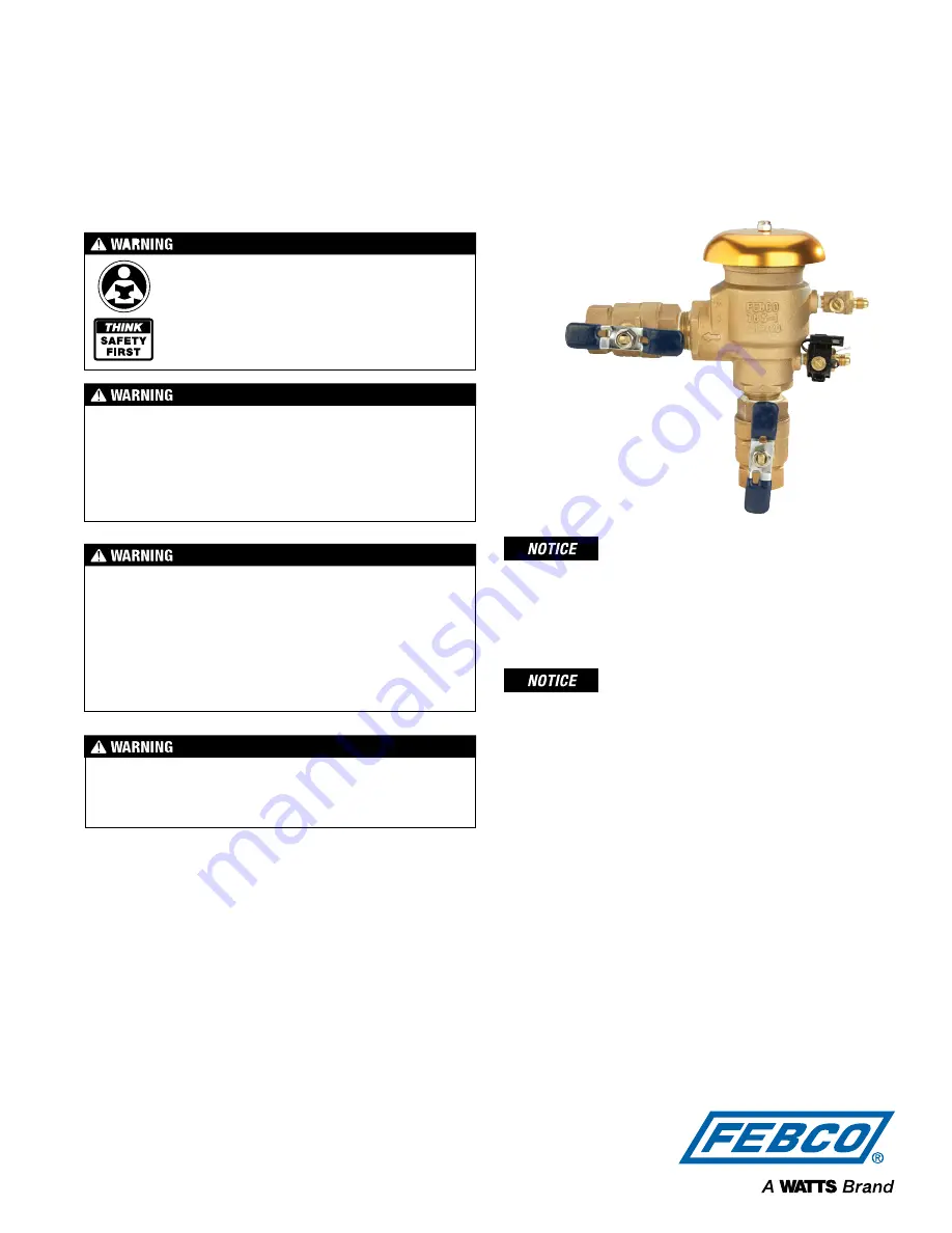
FEBCO Series 765 Pressure Vacuum Breakers are used to pro­

tect against health hazard and non-health hazard backsiphonage 

conditions in industrial plants, cooling towers laboratories, laundries, 

swimming pools, and lawn sprinkler systems. 
Series 765 includes a freeze sensor to indicate when temperature 

nears the freezing point. The sensor relays a signal to building/irrigation 

management systems when temperature crosses the preset threshold. 

Freeze alerts are distributed according to BMS/IMS applications, 

helping facility personnel take action to reduce or eliminate PVB 

replacement or repair. 

765-FZ

An add-on connection kit is required to activate the freeze sensor. 

Without the connection kit, the sensor is a passive component that 

has no communication with any other device. (The kit can also be 

used to retrofit existing installations. For ordering details, see “Add-

on/Retrofit Sensor Connection Kit.” 

Use of the freeze sensor and activation kit with FZ models does not 

replace the need to comply with all required instructions, codes, and 

regulations related to installation, operation, and maintenance of the 

PVB assembly. 

Watts

®

 is not responsible for the failure of alerts due to connectivity 

or power issues. 

Contents 

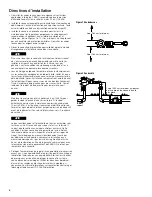
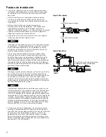
Installation Guidelines  . . . . . . . . . . . . . . . . . . . . . . . . . . . . . . . . . . . . . . 2 

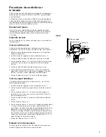
Field Testing Procedure . . . . . . . . . . . . . . . . . . . . . . . . . . . . . . . . . . . . . 3 

Service Procedure . . . . . . . . . . . . . . . . . . . . . . . . . . . . . . . . . . . . . . . . . 4 

Parts . . . . . . . . . . . . . . . . . . . . . . . . . . . . . . . . . . . . . . . . . . . . . . . . . . . 5 

Troubleshooting. . . . . . . . . . . . . . . . . . . . . . . . . . . . . . . . . . . . . . . . . . . 6 

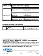
Add-on/Retrofit Sensor Connection Kit . . . . . . . . . . . . . . . . . . . . . . . . . 6 

Summary of Contents for FEBCO 765

Page 1: ...eze event and cannot prevent a freeze event from occurring User action is required to prevent freeze conditions from causing product and or property damage FEBCO Series 765 Pressure Vacuum Breakers ar...

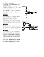
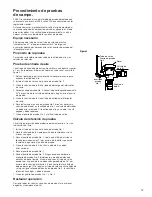
Page 2: ...valve to pressurize the unit Slowly open the outlet ball valve to fill the downstream line Maintain the downstream pressure above 5 psi 34 kPa to keep the spring loaded air inlet poppet closed If the...

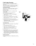
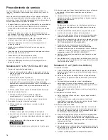
Page 3: ...m breaker 6 Slowly open test cock No 2 while watching the poppet in the air inlet The poppet must unseat If the air inlet does not open it is sticking and must be repaired 7 Close test cock No 2 and r...

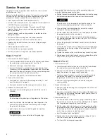
Page 4: ...sembly into the valve body Position the spring into the recessed area on the top side of the check assembly In some cases it may be easier to position the spring on the check assembly before positioni...

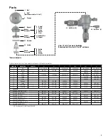
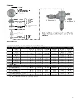
Page 5: ...6 1024564 1024564 6 O Ring 1101068 1101068 398 140 72 398 140 72 398 247 72 398 247 72 7 Spring 630 096 630 096 10 Stem 200 767 200 767 13 Retainer 300 096 300 096 300 088 300 088 14 Spring 630 108 6...

Page 6: ...in material and workmanship under normal usage for a period of one year from the date of original shipment In the event of such defects within the warranty period the Company will at its option replac...

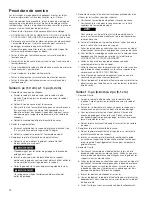
Page 7: ...e les conditions de gel ne causent des dommages au produit et ou la propri t Les casse vides pression FEBCO de la s rie 765 sont utilis s pour la protection contre les conditions de siphonnement rebou...

Page 8: ...robinet bille de sortie pour remplir le conduit en aval AVIS Maintenez la pression en aval sup rieure 5 psi 34 kPa pour garder le clapet d entr e d air ressort ferm Si le clapet antiretour ne parvient...

Page 9: ...ment le robinet d essai n 2 tout en surveillant le clapet dans l entr e d air Le clapet doit se d gager Si l entr e d air ne s ouvre pas elle est bloqu e et doit tre r par e 7 Fermez le robinet d essa...

Page 10: ...emble de clapet dans le corps de vanne Positionnez le ressort dans la zone encastr e sur le c t sup rieur de l ensemble de clapet AVIS Dans certains cas il peut tre plus facile de positionner le resso...

Page 11: ...2 300 093 300 089 300 089 300 083 300 083 4 Boulon 6 1024564 1024564 6 Joint torique 1101068 1101068 398 140 72 398 140 72 398 247 72 398 247 72 7 Ressort 630 096 630 096 10 Tige 200 767 200 767 13 Ba...

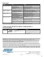
Page 12: ...un indicateur du seuil de gel pour les ensembles de casse vide pression dans une configuration BMS IMS Garantie limit e FEBCO la Soci t garantit que chacun de ses produits est exempt de vice de mat ri...

Page 13: ...ocurra la congelaci n Se requiere la acci n del usuario para evitar que las condiciones de congelaci n causen da os al producto y o a la propiedad Los interruptores de presi n y vac o PVB FEBCO Serie...

Page 14: ...a v lvula de bola de salida para llenar la l nea corriente abajo AVISO Mantenga la presi n corriente abajo por encima de 5 psi 34 kPa para mantener cerrada la v lvula de asiento accionada por la v lvu...

Page 15: ...vac o 6 Abra lentamente el puerto de prueba No 2 mientras observa la v lvula de obturador en la entrada de aire La v lvula de obturador no debe estar asentada Si la entrada de aire no se abre se est...

Page 16: ...en el cuerpo de la v lvula Coloque el resorte en el rea empotrada en la parte superior del conjunto de retenci n AVISO En algunos casos puede ser m s f cil colocar el resorte en el conjunto de retenci...

Page 17: ...2 Dosel 300 092 300 093 300 089 300 089 300 083 300 083 4 Perno 6 1024564 1024564 6 Junta t rica 1101068 1101068 398 140 72 398 140 72 398 247 72 398 247 72 7 Resorte 630 096 630 096 10 V stago 200 7...

Page 18: ...ce este kit para agregar un indicador del umbral de congelaci n para los conjuntos de PVB en una configuraci n de BMS IMS Garant a limitada FEBCO la Empresa garantiza que todos los productos no presen...

Reviews: