


DRD6 v2
Wireless Room Scene Controller
Installation Instructions
Specifications
Operating Voltage . . . . . . . . . . . . . . . . . . . . .120/277VAC, 60Hz
Operating Temperature . . . . . . . . 32°F to 104°F (0°C to 40°C)
TROUBLESHOOTING
During house ID binding, the LED is not flashing on some devices.
• If LED is solid green before initiating House ID binding:
The device already has another House ID. Reset it to the factory default so
that it can be bound to the desired House ID. Resetting to factory defaults
is described in “I made a confi guration mistake. I need to start over.”
• If LED is solid yellow after initiating House ID binding:
The device may be out of range of the initiating device. Add
a MRR2G Wireless Repeater to boost signal range.
During binding or customizing, all LEDs stop flashing before I press .
The 5 minute binding process timer may have expired. Restart the timer
by repeating steps 1 and 2 of the procedure you were using. Notice that
the devices you previously excluded are flashing green; those included are
flashing yellow; simply finish the process from where you left off.
The device LED flashes red when I press .
The house or room configuration may be locked.
Go to any house level scene controller and simultaneously press
and but-
tons B and E until the scene controller LED flashes GREEN.
Go back to the previously locked device and press
.
• If it flashes green or yellow, you have unlocked the house configuration.
• If the device still flashes red, the configuration may be locked
by a room level scene controller such as the DRD6 or MRH6G.
Go to the room scene controller and simultaneously press
and buttons
B and E until the scene controller LED flashes GREEN. (See LOCK ROOM
CONFIGURATION.)
Go back to the previously locked device and press
.
• If it flashes green or yellow, you have unlocked the room configuration.
• If the device still flashes red, the configuration may be locked by another
room level scene controller in the house. Repeat the procedure from dif-
ferent controllers until the device is no longer flashing red.
I made a configuration mistake. I need to start over.
To reset any Miro wireless device to factory default settings, press and
hold -
- until the LED changes to solid yellow (approximately 10 seconds).
During the process, the LED flashes yellow. When complete, it becomes solid
yellow. The device can then be reconfigured, exactly like any new device.
CLEANING
Clean using a cloth dampened only with water and a little mild detergent. Use of
solvents or hydrocarbon-based cleaners may cause permanent damage.
MORE SCENES
Up to 15 scenes are available per room. Each room level controller can access a
set of 5 scenes. The DRD6 is assigned to scenes 1-5 when shipped. Changing to
scene set 6-10 lets you record 5 more scenes; changing to scene set 11-15 lets
you record another 5 scenes. Binding three room level controllers (MRH6G or
DRD6) to the room and assigning each to a different scene set, lets you dedicate
a controller to each scene set. You can bind more room scene controllers to the
room to control the same scenes from multiple locations.
All room scene controllers that have the same scene set assignment operate the
5 scenes in the same way as all other room scene controllers programmed for the
same set. Scene buttons on controllers with scene sets 6-10 and 11-15 default to
0%/All room devices OFF. Use ROOM BINDING and CUSTOMIZING OPERATION
procedures to set up the additional scene controllers.
To assign scenes 6-10, simultaneously press
and
B
until
the LED blinks twice (about 2 seconds).
To assign scenes 11-15, simultaneously press
and
C
until the LED blinks twice (about 2 seconds).
To change the assignment back to scenes 1-5,
simultaneously press
and button
A
until the LED blinks
twice (about 2 seconds).
A
= 1-5 (default)
B
= 6-10
C
= 11-15
LOCK ROOM CONFIGURATION
The Lock Configuration function operates from a wireless Miro room level
controller, and prevents the Miro wireless devices in the room from being
reprogrammed. Other operations such as dimming, switching and scene recall
are not affected.
When the configuration is locked, if
is pressed and held on any Miro wireless
device, the device’s LED flashes red and the command is ignored.
To lock the configuration:
Go to any room scene controller. Simultaneously press
and buttons
B
and
E
until the LED flashes (about
2 seconds) to toggle in and out of Lock Configuration.
• If the mode changes from unlocked to locked,
the LED flashes
red
for 2 seconds, indicating that
configuration is now locked.
• If the mode changes from locked to unlocked, the
LED flashes
green
for 2 seconds, indicating that
configuration is now unlocked.
CUSTOMIZING OPERATION
Modify and Save the Light Levels of a Scene
1. Change lighting levels as desired by pressing or
on individual devices.
2. Press and hold the scene button until the LED flashes once (about
2 seconds) to save the new settings.
Removing or Adding Devices to a Scene
1. Press on the DRD6 until the LED begins flashing (about 2 seconds).
2. Press the scene button that you wish to program. LEDs on all wireless Miro
devices begin to flash. You now have 5 minutes to complete this process.
3. To include or exclude a device in the scene press
on the device until the
LED changes color.
Yellow
flashing LED = Included in the active scene
Green
flashing LED = NOT included in the active scene
If you get to a device and it is NOT flashing, see TROUBLESHOOTING.
NOTE:
You must include devices that are off in the room scene if you want
them to turn off when that scene is recalled.
4. Return to the DRD6 used in step 1. Press
for 2 seconds — the status LED
stops flashing, then all the status LEDs in the house turn green.
Removing or Adding Devices to the Paddle “On” Function
1. Press on the DRD6 until the LED begins flashing (about 2 seconds).
2. Tap the paddle on the DRD6. The LEDs on all the Miro wireless devices
begin to flash. You now have 5 minutes to complete this process.
3. To include or exclude a device press
on the device until the LED changes
color.
Yellow
flashing LED = Included in paddle operation
Green
flashing LED = NOT included in paddle operation
If you get to a device and it is NOT flashing, see TROUBLESHOOTING.
4. Return to the DRD6 used in step 1. Press
for about 2 seconds — the status
LED stops flashing, then all the status LEDs in the house turn green.
5. To test, tap on any room scene controller that is bound to the same room to
switch included devices to on (dimmers go to full bright).
Removing or Adding Devices to the Paddle “Off” Function
1. Press on the DRD6 until the LED begins flashing (about 2 seconds).
2. Tap the paddle on the DRD6. The LEDs on all the Miro wireless devices
begin to flash. You now have 5 minutes to complete this process.
3. See step 3 above.
4. See step 4 above.
5. To test, tap on any room scene controller that is bound to the same room to
switch or fade included devices to off (dimmers go to 0%).
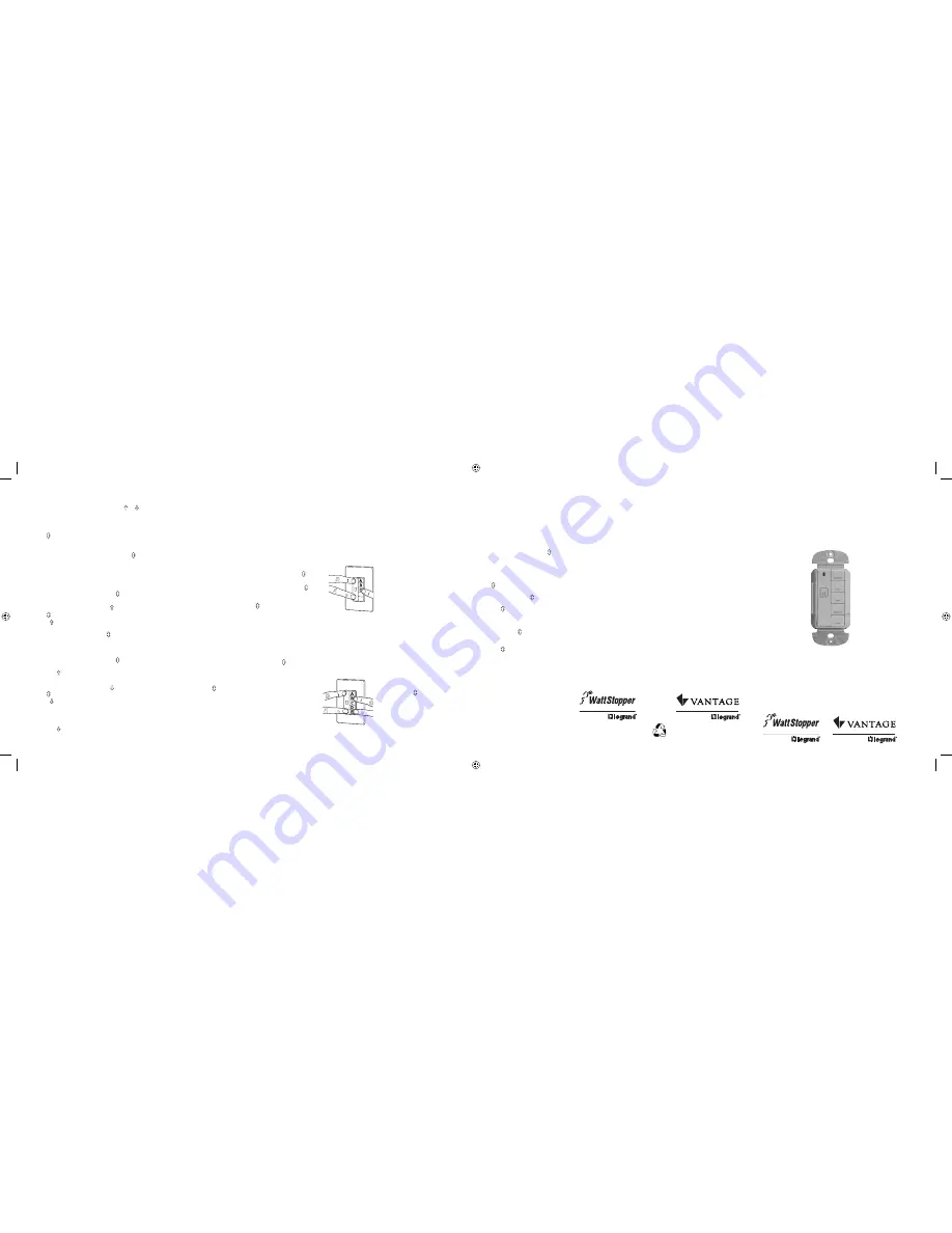
Assigning the DRD6
for scene set 11-15
Patents pending
POWER FAIL MEMORY
After a power failure, all Miro devices automatically return to the state they
were in immediately prior to loss of power. All house binding and scene control
information is preserved.
FCC Notice
This equipment has been tested and found to comply with the limits for a Class B
digital device, pursuant to part 15 of the FCC Rules. These limits
are designed to provide reasonable protection against harmful interference
in a residential installation. This equipment generates, uses and can radiate radio
frequency energy and, if not installed and used in accordance with
the instructions, may cause harmful interference to radio communications.
However, there is no guarantee that interference will not occur in a particular
installation. If this equipment does cause harmful interference to radio or
television reception, which can be determined by turning the equipment off and
on, the user is encouraged to try to correct the interference by one or more of the
following measures:
• Reorient or relocate the receiving antenna.
• Increase the separation between the equipment and receiver.
• Connect the equipment to an outlet on a circuit different from that to which the
receiver is connected.
• Consult the dealer or an experienced radio/TV technician for help.
Caution:
Any changes or modifi cations to this device not explicitly approved by
manufacturer could void your authority to operate this equipment.
WARRANTY INFORMATION
Manufacturer warranties its products to be free of defects in materials and
workmanship for a period of fi ve (5) years. There are no obligations or liabilities
on the part of manufacturer for consequential damages arising out of, or
in connection with, the use or performance of this product or other indirect
damages with respect to loss of property, revenue or profi t, or cost of removal,
installation or reinstallation.
2800 De La Cruz Blvd.
Santa Clara, CA 95050
Phone: 800.879.8585
www.wattstopper.com
Please
Recycle
1061 South 800 East
Orem, UT 84057
Phone: 800.555.9891
www.vantagecontrols.com
07479r2 9/2007
Watt Stopper Customers contact:
Vantage Customers contact:
ii_DRD6v2 07479r2.indd 1-5
ii_DRD6v2 07479r2.indd 1-5
9/24/2007 4:17:12 PM
9/24/2007 4:17:12 PM


