


INSTALLATION OF CONE SINK INTO DISH OR WORKTABLE
1.
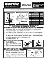
(See Figures 1 and 2.) Locate hole center as shown on Figure 2. Cut a “C” (Figure 2) diameter hole in dish or work table, a minimum of 2”
from the inside front edge (operator’s side). Hole can be cut with a “nibbler” after a knockout hole 1
1
/
2
” diameter has been punched.
2.
Lift cone to underside of table with cone flange overlapping all around (Figures 1 and 3).
3
. Check alignment of cone spray fittings to be sure they are in the proper position. For 15” and 18” cones, position such that holes are located
to right and left side of operator. (See Figure 7 for location.)
4
. Tack weld, spot weld, bolt, or rivet flange of cone sink to underside of dish or work table. If bolted or riveted, smooth top surface and wash-
solder around bolt or rivet heads and sand smooth.
5
. Bead weld or solder and wash-solder all around where the table joins flange of cone sink for a clean, watertight, sanitary installation.
6
. The cone sink has been designed with the step, as shown in Figure 3. In the welding or soldering operation required to assemble the cone
sink to the dish or work table, every attempt should be made to keep the recessed, flat portion of the cone free of the weld or solder materi-
al. This will minimize the clean-up time required and provide a smooth, flat surface for any cover.
7
. Minimum installation criteria:
• Minimum clearance between left and right side of waste disposer and side wall: 18 inches.
• Minimum clearance to back wall: 10 inches.
• No front panel/door between waste disposer installation cavity under a sink/dish table and room.
SPRAY-RINSE INSTALLATION
1.
Locate center (Figures 1 and 2).
2
. Drill 7/16” diameter hole through center.
3
. Assemble 7/8” punch and tighten bolt head, as illustrated,
until the die pierces the stainless steel, leaving a clean
opening of 7/8”.
4
. Place body valve and base in position, assemble
washer
and
locknut
as shown in Figure 5.
5
. Attach vol-temp assembly to the projecting nipple.
POSITIONING AND INSTALLATION
OF COMMERCIAL DISPOSER
1.
Subassemble plumbing for swirl sprays as shown in detail in Figure 6,
and as shown assembled on final unit in Figure 7.
2
. Slide Hush Cushion
®
up over edge of flange on cone sink. The inner
edge of this Hush Cushion
®
is chamfered to facilitate this operation.
3
. Slide one clamp ring over Hush Cushion
®
, place between two upper beads
and tighten, this firmly attaches the Hush Cushion
®
to the cone sinks.
NOTE
: On the six inch opening only to make certain that the Hush Cushion
®
is not mounted upside down, look down into the cone sink from above the
work table and check that the wording is readable on the center plug on the
Hush Cushion
®
. This reads, “Remove before using”.
COMMERCIAL
DISPOSER MODELS
2000, 3000, 5000
AND 10000
INSTALLATION
INSTRUCTIONS
BEFORE INSTALLING, READ ENTIRE INSTRUCTIONS CAREFULLY.
RISK OF INJURY TO PERSONS FROM HAZARDOUS MOVING PARTS. SERIOUS INJURY POSSIBLE IF
NOT PROPERLY INSTALLED WITH A HOPPER OR A CONE SPECIFIED IN THE INSTRUCTION MANUAL.
IF YOU ARE REPLACING AN OLD DISPOSER GO TO
POSITIONING AND
INSTALLATION OF COMMERCIAL DISPOSER
MODEL 6T
2216
2215
2211
12” CONE
15” CONE
18” CONE
A
10
1
/
4
”
11
3
/
4
”
13
1
/
4
”
B
3
1
/
2
”
3
1
/
2
”
3
1
/
2
”
C
13
1
/
2
”
16
1
/
2
”
19
1
/
2
”
MODEL 9T
2216
2215
2211
12” CONE
15” CONE
18” CONE
A
12
7
/
8
”
12
7
/
8
”
12
7
/
8
”
B
6
1
/
8
”
4
5
/
8
”
3
1
/
8
”
C
13
1
/
2
”
16
1
/
2
”
19
1
/
2
”
FIG. 1
FIG. 2
FIG. 4
FIG. 5
FIG. 3
FIG. 6
BODY
VALVE
7/8” PUNCH
BASE
WASHER
DISH TABLE
CONE SINK
APPROX.
30”
APPROX. 14”
9” MIN.
6” MIN.
2” TO 4”
6”
A
6-5/8”
No. 9T
SPRAY
RINSE
No. 6T
SINK
HOLE
C DIA.
SPRAY
RINSE
HOLE
A
B
LOCKNUT
FLAT PORTION
OF CONE SINK
GLOBE VALVE 1/2”
1/2” COPPER
TUBING
1/2” COPPER
TUBING
1/2” TUBE
FITTING
1/2” TUBE
FITTING
1/2” CLOSE
NIPPLE
NIPPLE 1/2” X 6”
1/2” X 4” NIPPLE
1/2” “T”
1/2” “T”
1/2” CLOSE NIPPLE
SPRAY RINSE


