Wasp WPL206 Series, User Manual
Get ready to maximize your productivity with the Wasp WPL206 Series! This innovative labeling solution will revolutionize your business operations. To learn more about its extensive features and functionalities, make sure to download the user manual for free from our website. Enhance your workflow with this user-friendly manual today!
Share
Download


Reviews:
No comments
Related manuals for WPL206 Series

C910
Brand: Oki Pages: 33

C910
Brand: Oki Pages: 52

C910
Brand: Oki Pages: 11

120
Brand: OKIDATA Pages: 58
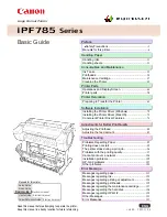
image Prograf iPF785 Series
Brand: Canon Pages: 136

A1
Brand: GBC Pages: 110

M Series
Brand: Xerox Pages: 2

MK2
Brand: V-King Pages: 41

2060 WX
Brand: QMS Pages: 208

CM3700 Series
Brand: BenQ Pages: 6

C782dn
Brand: Lexmark Pages: 4

C542
Brand: Oki Pages: 255

9688
Brand: Avery Dennison Pages: 2

biodoc-it 2
Brand: UVP Pages: 22

bizhub 215
Brand: Konica Minolta Pages: 8

4035e
Brand: Savin Pages: 132

Adaptive CMYK+ Kit
Brand: Xerox Pages: 48

PIXMA MP268
Brand: Canon Pages: 37


