


Reviews:
No comments
Related manuals for implantmed SI-923

3200
Brand: Waterwise Pages: 12

700
Brand: ParaBody Pages: 38

Drying Cabinet
Brand: Malmet Pages: 14

EVO Series
Brand: Zempire Pages: 2

RC Series
Brand: Parker Pages: 5

Fyrite INSIGHT
Brand: Bacharach Pages: 31

Monoxor III
Brand: Bacharach Pages: 2

iSave 21
Brand: Danfoss Pages: 106

PANDA
Brand: GE Pages: 212

VM3D
Brand: ABB Pages: 4

Pro hunter 2525
Brand: SprotDog Pages: 28

PRO IS2
Brand: Unika Pages: 8
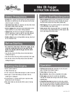
Mini DB
Brand: B&G Pages: 2

SnapTable PRO Hyper-Lite
Brand: SWENSON SHEAR Pages: 12

ZK-PROTECT
Brand: ZAMST Pages: 14

MONSTER HAWK
Brand: Elliott Pages: 46

GF222T
Brand: KUHN Pages: 44

BoilerMag XT Series
Brand: Spear & Jackson Pages: 8


