Wallenstein BXM32EU, Operator'S Manual
The Wallenstein BXM32EU Operator's Manual is essential for properly maintaining and operating your equipment. This comprehensive manual provides detailed instructions on how to use and care for your product. You can download the manual for free from manualshive.com, ensuring you have all the information you need at your fingertips.
Share
Download


Reviews:
No comments
Related manuals for BXM32EU
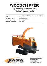
A530
Brand: Jensen Pages: 72
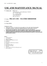
PELLICANO
Brand: FALC Pages: 16

TS 2222 CD
Brand: Opus Pages: 10

PS 705.4 CC
Brand: Olympia Pages: 100

9043623
Brand: P.Lindberg Pages: 32

94407
Brand: GÜDE Pages: 104

282
Brand: shredder Pages: 14

330s
Brand: Shredmaster Pages: 28

4108
Brand: IDEAL Pages: 28

Shredmaster 6120S
Brand: GBC Pages: 4

40204
Brand: Dahle Pages: 22

1323P
Brand: SEM Pages: 15

Shredstar BS12C
Brand: HSM Pages: 4

C13RT
Brand: Hansa Pages: 28

FBT400
Brand: Feider Machines Pages: 21

ShredMaster GDS2213
Brand: GBC Pages: 18

B087QCPKSW
Brand: Amazon Pages: 3

0201 OMD
Brand: IDEAL Pages: 40


