Walinga 510, Maintenance Manual
The Philips 510 Quick Start Manual is a comprehensive user manual designed to help you swiftly set up and operate your Philips 510 device. This manual is available for free download at manualshive.com, ensuring you have all the necessary instructions at your fingertips.
Share
Download


Reviews:
No comments
Related manuals for 510

510 Series
Brand: Lamson Pages: 4

4500 Series
Brand: Gardner Denver Pages: 45

VX1
Brand: Vax Pages: 16

BL6000
Brand: Nakayama Pages: 13

GTV Series
Brand: Pakole Pages: 28

PS300
Brand: MADVAC Pages: 182

51626
Brand: Lawn-Boy Pages: 8

GBV 325
Brand: Partner Pages: 12

GBV 345
Brand: Partner Pages: 12

510
Brand: Lamson Pages: 3

4014N
Brand: Makita Pages: 8

BUB143
Brand: Makita Pages: 6

DUB361
Brand: Makita Pages: 6

RBL500
Brand: Makita Pages: 9

BUB182Z
Brand: Makita Pages: 16

EB7650TH
Brand: Makita Pages: 35

BBX7600
Brand: Makita Pages: 66
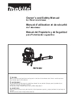
PM7650H
Brand: Makita Pages: 84


