Waldorf microQ, User Manual
The Waldorf microQ is a powerful synthesizer that offers an extensive range of sonic possibilities. Unlock the full potential of this exceptional instrument by accessing the free, comprehensive User Manual. Download it now from our website and delve deeper into the world of sound creation with the microQ.
Share
Download


Reviews:
No comments
Related manuals for microQ
120X
Brand: dbx Pages: 12

Spherical Wavetable Navigator
Brand: 4ms Company Pages: 4

ADS-7
Brand: AVP Synthesizers Pages: 8

HP 8904A
Brand: HP Pages: 139
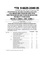
3325A
Brand: HP Pages: 23

3326A
Brand: HP Pages: 146
3320A
Brand: HP Pages: 179

HP 8904A
Brand: HP Pages: 281

Alfa JUNO-2
Brand: Roland Pages: 54

HG-16 black
Brand: Audiospektri Pages: 33

K4R
Brand: Kawai Pages: 104

CGS738
Brand: Elby Designs Pages: 4

Grendel Grenadier RA-99
Brand: Rare Waves Pages: 22

MMO-4
Brand: Nozoid Pages: 9

MMO-3
Brand: Nozoid Pages: 15

OCS-2
Brand: Nozoid Pages: 17

Grenadier RA-9
Brand: Grendel Pages: 14

SYNTH300-TRIG
Brand: Furaxa Pages: 31


