Vzense DCAM800, User Manual
The Vzense DCAM800 user manual is available for free download on our website. This comprehensive manual provides step-by-step instructions and detailed information on how to maximize the features and functionalities of your DCAM800. Gain a better understanding of your product's capabilities and download the manual from manualshive.com.
Share
Download


Reviews:
No comments
Related manuals for DCAM800

A18
Brand: Tamron Pages: 9

SP-500
Brand: Olympus Pages: 1
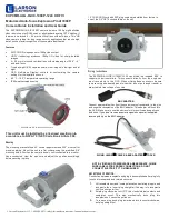
EXPCMR-ALG-OZ-IC-1080P-1224 HD-TVI
Brand: Larson Electronics Pages: 4
AF 5078MS
Brand: AgfaPhoto Pages: 2

M1104
Brand: Axis Pages: 56

C754
Brand: DB POWER Pages: 28

BOBCAT B0610C
Brand: Imperx Pages: 329

WINDER 2
Brand: Olympus Pages: 101

ON-HS94A
Brand: Cube Pages: 42

GoSafe 318
Brand: Papago Pages: 100

StarShoot AllSky Camera II
Brand: Orion Pages: 4

PerfectView LCD250
Brand: Waeco Pages: 184

GST-894i
Brand: Orion Technology Pages: 4

T199104
Brand: FLIR Pages: 10

QN65B/4F
Brand: VESTEL Pages: 76

PVC720
Brand: Preco Pages: 5

XDS-1060
Brand: IAdea Pages: 25

Lumix DMC-FX30P
Brand: Panasonic Pages: 52


