VXI Technology CT-100C Series, User Manual
The VXI Technology CT-100C Series offers high-quality user manuals for free download. Access the manual for detailed instructions and information on utilizing the product's features. Download the user manual from our website to get the most out of your CT-100C Series device.
Share
Download


Reviews:
No comments
Related manuals for CT-100C Series

FACT NG4
Brand: CommScope Pages: 11
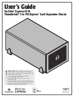
Echo Express SE III
Brand: Sonnet Pages: 14
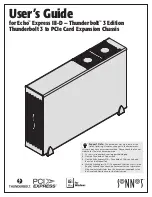
Echo Express III-D Thunderbolt 3 Edition
Brand: Sonnet Pages: 14
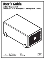
echo express SE II
Brand: Sonnet Pages: 16
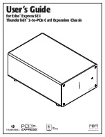
Echo Express SE I
Brand: Sonnet Pages: 16

D3654-B
Brand: Fujitsu Pages: 12
D3654-B
Brand: Fujitsu Pages: 29

SnapExpansion DX Series
Brand: Overland Storage Pages: 3

SnapServer EXP E2000 Expansion Array
Brand: Overland Storage Pages: 2


