background image

This Manual is prepared for the use of trained Vulcan Service
Technicians and should not be used by those not properly qualified.

This manual is not intended to be all encompassing. If you have not
attended a Vulcan Service School for this product, you should read,
in its entirety, the repair procedure you wish to perform to
determine if you have the necessary tools, instruments and skills
required to perform the procedure. Procedures for which you do not
have the necessary tools, instruments and skills should be
performed by a trained Vulcan Service Technician.

The reproduction, transfer, sale or other use of this Manual, without
the express written consent of Vulcan, is prohibited

.

This manual has been provided to you by ITW Food Equipment
Group LLC ("ITW FEG") without charge and remains the property
of ITW FEG, and by accepting this manual you agree that you will
return it to ITW FEG promptly upon its request for such return at
any time in the future.
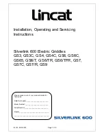
948RX

SERVICE  MANUAL

HEAVY DUTY GAS GRIDDLES

MODELS

924RX

MSA24

936RX

MSA36

948RX

MSA48

960RX

MSA60

972RX

MSA72

For additional information on Vulcan-Hart Company or to locate an authorized parts
and service provider in your area, visit our website at www.vulcanhart.com.

A product of VULCAN-HART

LOUISVILLE, KY 40201-0696

F25383 (510)

Summary of Contents for 924RX

Page 1: ...Service Technician The reproduction transfer sale or other use of this Manual without the express written consent of Vulcan is prohibited This manual has been provided to you by ITW Food Equipment Gr...

Page 2: ...mentary Power Switch 900rx 5 Electric Igniter 900rx 6 BASO Safety Valve 6 Thermostat Valve Assembly 6 Burner 8 Pilot Thermocouple Assembly 8 SERVICE PROCEDURES AND ADJUSTMENTS 9 Calibration 9 Pilot Ad...

Page 3: ...at is controlled by a momentary power switch The power switch turns the electric ignition system off and on only and will only supply power to the igniters when held down in the ON position The burner...

Page 4: ...421 or equivalent Adapter to test thermocouple Johnstone Supply Part No H23 226 or equivalent COMPONENT LOCATION 1 Pilot electric ignition system control switch RX only 2 Power cord RX only 3 Thermost...

Page 5: ...h the front panel to see both pilot burners and griddle burners Move any flexible gas tubing or capillary tubing that may obstruct the sight holes Back Panel NOTE It will be necessary to remove the ba...

Page 6: ...d pipe and valve for reassembly later NOTE Ignition wires must be routed in front of valves as shown to prevent them from touching hot heat shield 3 Disconnect all gas lines and thermocouple from valv...

Page 7: ...om old capillary tube and install on new thermostat 8 Secure end of insulator sleeve to thick end of capillary tube with metal tape as shown 9 Slide capillary tube all the way into slot underneath gri...

Page 8: ...n reverse order 6 Adjust as outlined in BURNER ADJUSTMENT PILOT THERMOCOUPLE ASSEMBLY 1 Remove FRONT PANEL 2 From underneath the front of the griddle remove screw securing pilot assembly bracket 3 Car...

Page 9: ...he griddle with all points located 12 back from the front edge of the griddle plate NOTE Use of infrared thermometers is not recommended These devices are highly sensitive to surface color clean or di...

Page 10: ...so that all burners are on 7 Turn all the equipment on the same supply line on 8 Check gas pressure 9 Gas pressure should read 4 W C for natural and 10 W C for propane gas If not correct refer to GAS...

Page 11: ...ADJUSTMENT For efficient burner operation it is important that a proper balance of gas volume and primary air supply is maintained to give complete combustion Insufficient air supply results in a yell...

Page 12: ...meter lead to pin on thermocouple adapter and meter lead to thermocouple 5 Light pilot flame 6 Verify that thermocouple is sufficiently immersed in flame Adjust pilot valve to allow more gas flow if...

Page 13: ...ELECTRICAL OPERATION ELECTRICAL OPERATION ELECTRICAL DIAGRAM F25383 510 Page 13 of 16...

Page 14: ...ELECTRICAL OPERATION F25383 510 Page 14 of 16...

Page 15: ...pressure incorrect or fluctuating 2 Obstructed flue 3 Gas orifice obstructed improperly aligned spaced or incorrect 4 Burner malfunction One or more burners have lower flame level than the others 1 Ch...

Page 16: ...TROUBLESHOOTING F25383 510 Printed in USA...

Reviews: