background image

Service Information

Document Title:

Function Group:

Information Type:

Date:

Track  motor  relief  valve, 
replacing

Service Information

2014/6/12 

Profile:
EXC, EC210B LC [GB]

Track motor relief valve, replacing

Op nbr 441-112

1. Park the machine in the service position F, see 

.

091 Service positions

2. When  the  engine  is  running,  the  hydraulic  line  is  under  high  pressure.  Stop  the  engine,  and  remove the  residual 

pressure inside the hydraulic line by the travel control lever smoothly for 3 ~ 4 times with ignition switch at "ON" 
position.
NOTE!
Remove the residual pressure inside the hydraulic tank by pressing the air breather on the hydraulic tank.

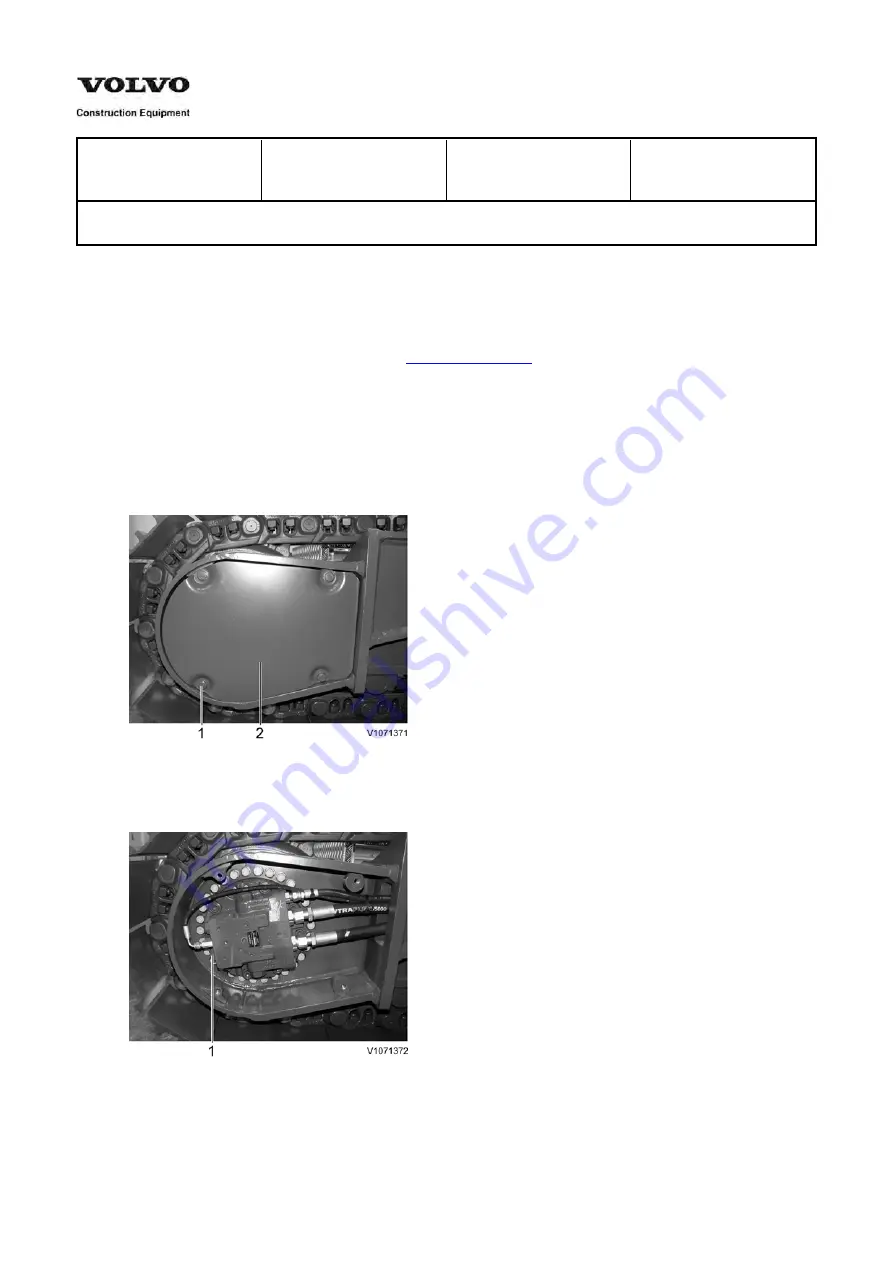
3. Remove screws (1) and motor cover (2).

Figure 1
Removal, motor cover

4. Remove track motor relief valve (1).

Figure 2
Removal, relief valve

5. Install a new relief valve.

6. Check relief valve pressure of the track motor, and adjust if necessary

Summary of Contents for EC210B LC

Page 1: ...e is under high pressure Stop the engine and remove the residual pressure inside the hydraulic line by the travel control lever smoothly for 3 4 times with ignition switch at ON position NOTE Remove the residual pressure inside the hydraulic tank by pressing the air breather on the hydraulic tank 3 Remove screws 1 and motor cover 2 Figure 1 Removal motor cover 4 Remove track motor relief valve 1 F...

Page 2: ...icate proper positioning during reassembly Take care not to mix parts of sub assemblies Thoroughly clean all parts and the inside of the casings Inspect and analyze all failures Brake valve and motor section 1 Prior to disassembly install the motor on a rotary work stand Drain the hydraulic oil gear oil NOTE Oil pan size 4 liter 8 liter Figure 1 Track motor 2 Remove the relief valve from rear flan...

Page 3: ...Figure 2 Relief valve removal 3 Remove screws 243 Figure 3 Screws removal 4 Remove rear flange 201 from spindle 302 NOTE Take care not to remove shaft 2 ...

Page 4: ...ngs 13 and bearing 50 from rear flange 201 and hydraulic motor Remove O rings 329 from spindle 302 NOTE Do not reuse O rings 329 after removal Figure 5 Bearing removal Brake valve 6 Counterbalance spool removal Remove plugs 224 from rear flange 201 Remove O ring 236 from plug 224 NOTE Do not reuse O ring 236 after removal ...

Page 5: ...alance spool 223 and the sliding surface of rear flange 201 Since rear flange 201 and counterbalance spool 223 are of the selective fitting type replace them together as a kit even if only one of the two parts is damaged Figure 7 Plug removal 7 Check valve removal Remove plugs 226 from rear flange 201 Figure 8 Plug removal Remove springs 230 and check valves 227 from rear flange 201 ...

Page 6: ... O ring 237 from plug 226 NOTE Do not reuse O ring 237 after removal 8 Two speed valve removal Remove plugs 257 from rear flange 201 Figure 11 Spool removal Remove spool 263 and spring 266 from rear flange 201 Remove O rings 295 from plugs 257 NOTE Do not reuse O ring 295 after removal 9 Removal of internal parts Figure 12 ...

Page 7: ... NOTE Take care not to damage the piston hole NOTE Since rear flange 201 and piston 281 are of the selective fitting type replace them together as a kit Remove plug 282 O ring 283 284 Figure 14 Plug removal NOTE Do not reuse O ring after removal Remove steel balls 285 from rear flange 201 Figure 15 Steel ball removal 10 Relief valve removal ...

Page 8: ...om plug 104 Take out spring retainer 103 spring 106 and piston 101 in that order from sleeve 102 Remove seal 120 from piston 101 Disassemble the other side sleeve in the same method NOTE If the parts except O ring 110 and seal 120 need to be replaced the relief valve must be reset on a test bench Therefore replace the relief valve assembly Figure 17 Spring retainer removal Figure 18 Spring removal...

Page 9: ...removal WARNING Abrupt injection of compressed air may cause piston to pop out To ensure your safety apply a protective cover over the piston Figure 21 Apply the compressed air Remove brake piston 12 by injecting compressed air pressure 3 5 kgf cm2 into the parking brake access hole in spindle 302 ...

Page 10: ...ands and turn it two to three times in a clockwise and counterclockwise direction alternately to detach shoes 6 from swash plate 3 NOTE Be careful when removing the cylinder block that the pistons and needle rollers 51 do not fall into the spindle Hold cylinder block 4 with both hands and remove it from spindle 302 Remove swash plate 3 steel balls 67 from spindle 302 Remove the mating plates 16 an...

Page 11: ...e the swash plate 3 from spindle 302 Figure 25 Swash plate removal 14 Remove the drive shaft 2 from spindle 302 by striking the front part lightly with a plastic hammer Figure 26 Drive shaft removal 15 Remove the bearing 49 from drive shaft 2 ...

Page 12: ...safety apply a protective cover over the piston Figure 28 Steel ball and parallel pin removal 17 Remove the speed selector piston assembly piston 61 and shoe 62 from spindle 302 by feeding compressed air pressure 3 5 kgf cm2 into the access hole in spindle 302 Figure 29 Piston removal NOTE The rotary group parts must be replaced as a set Reference the parts catalog for details ...

Page 13: ...ress the axial centers of retainer I and washer to prevent the cylinder block from being damaged by contact NOTE Protect the sliding surface of the cylinder block with a rubber sheet NOTE Remove spring 14 only if it is to be replaced WARNING Do not release the press abruptly The spring could pop out and cause an injury Figure 31 Snap ring removal Slowly release the press until the spring force is ...

Page 14: ...Figure 32 Spring removal ...

Page 15: ...torque Item No Description Thread size Torque kgf m lbf ft 102 Sleeve PF 1 25 5 180 36 104 Plug PF 1 2 10 2 72 14 224 Plug M36 P 1 5 45 9 325 65 226 Plug M36 P 1 5 26 4 188 29 243 Screw M16 P 2 0 25 7 4 186 29 246 252 Plug PT 1 4 3 0 5 22 4 254 Plug NPTF 1 16 1 0 0 25 7 2 1 8 257 Plug PF 1 2 10 2 72 14 280 Plug PF 3 8 6 1 43 7 282 Plug PF 1 8 1 5 0 25 10 8 1 8 298 Plug PF 1 8 1 25 0 25 9 1 8 Brake...

Page 16: ... internal leakage to occur after reassembling and motor performance to deteriorate Figure 2 Counterbalance spool install Attach O ring 236 NOTE Apply grease to the O ring Install stopper 225 and spring 228 into both plugs 224 and tighten plugs 224 into rear flange 201 to the required torque 45 9 kgf m 325 65 lbf ft NOTE If either the rear flange 201 or spool 223 is to be replaced the entire assemb...

Page 17: ...mage to the bore section of the rear flange or the surface of the spool may cause internal leakage to occur after reassembling and motor performance to deteriorate Figure 4 Spool install Tighten plugs 257 into rear flange 201 to the required torque 10 2 kgf m 72 14 lbf ft Figure 5 Plug install 4 Shock relief valve parts Insert steel balls 285 into rear flange 201 Mount O rings 283 284 on plugs 282...

Page 18: ... very much for reading This is part of the demo page GET MORE Hydraulic System Setting Instructions Functional Description Electrical System And more Click Here BUY NOW Then Instant Download the Complete Manual ...

Reviews: