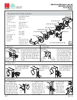
background image

Grade 1 Cylindrical 

Smartlock

Installation Instructions

Part Number: VPSLCS1

Summary of Contents for Grade 1 Cylindrical Smartlock

Page 1: ...Grade 1 Cylindrical Smartlock Installation Instructions Part Number VPSLCS1 ...

Page 2: ... door 1 Four 4 AA Batteries Not Included 2 2 Philips Head Screwdriver 3 5 16 Drill Bit Only required for ANSI Grade 1 Installation That is between 1 3 8 and 2 3 8 thick That has a 2 1 8 door prep That has 2 or 2 3 8 backset Before You Begin A Checklist ...

Page 3: ...e which Backset fits your installation 2 3 8 60mm or 2 3 4 70 mm 2 Fold installation template place it on the door and mark the holes 3 Drill the two 5 16 8mm holes for the mounting screws and securing B ANSI GRADE 1 Installation ONLY TEMPLATE FOLD LINE LATCH HOLE ...

Page 4: ...04 Ensure the latch bolt bevel faces the closing direction and secure the latch to the door using two 8 x 3 4 screws C Latch Installation CLOSING DIRECTION ...

Page 5: ...Determine the direction of your door Default is for a right hand door 2 Install the Lock Body Assembly using the correct diagram below D Lock Handing RIGHT HAND RIGHT HAND REVERSE LEFT HAND LEFT HAND REVERSE ...

Page 6: ...side Lever Catch Pin E To Change Direction to a Left Hand Door IF YOU HAVE A RIGHT HAND DOOR SKIP TO SECTION F OUTSIDE ASSEMBLY SCREWS OUTSIDE ASSEMBLY OUTSIDE LEVER CATCH PIN 2 Remove the four 4 Outside Assembly Screws and take out the assembly ...

Page 7: ...crews 3 Remove the inside lever using the Inside Lever Catch Pin 4 Remove the two 2 Inside Assembly screws and take out the Inside Assembly 5 Rotate the Inside Assembly 180 degrees 6 Replace the two 2 Inside Assembly Screws INSIDE LEVER CATCH PIN INSIDE ASSEMBLY INSIDE ASSEMBLY SCREWS ...

Page 8: ...t for Door Thickness CONVEX KEY ROTATE CLOCKWISE 2 Make sure the convex key should is facing the door and install the Outside Mounting Plate on lock body by rotating clockwise 3 Set the Catch Tool to the appropriate position on the Door Thickness Mark 4 Rotate the Outside Mounting Plate to the appropriate door thickness using Catch Tool ...

Page 9: ...09 1 Mount the Lock Body to the Outside Housing G Install Lock Housing IF THIS IS NOT AN ANSI GRADE 1 INSTALLATION REMOVE THE OUTER STUDS 2 Insert the Outside Housing Assembly in the door Outer Studs ...

Page 10: ...Housing M6 X 10 SCREWS 2 1 Mount the Lock Body to the Outside Housing 2 Insert the Outside Housing Assembly in the door 3 FOR ANSI Grade1 Installations only attach the Mounting Plate to the outer Studs 4 Make sure the Mounting Plate is aligned with the vertical center line and install it using two M5x38 screws ...

Page 11: ...side Housing Assembly to Mounting Plate using one Panhead M3X10 Screw 7 Install inside and outside Levers 8 Install four 4 AA alkaline batteries in the Battery Case 9 Install the Battery Case using a flathead M4x12 screw ...

Reviews: