Vivax Metrotech vLoc3-Pro, User Handbook Manual
The Vivax Metrotech vLoc3-Pro User Handbook Manual is available for download free of charge from our website. This comprehensive manual provides detailed instructions and insights on operating and optimizing the vLoc3-Pro device, allowing users to make the most of its advanced features and functionalities.
Share
Download


Reviews:
No comments
Related manuals for vLoc3-Pro

Freedom SW 2000
Brand: Xantrex Pages: 36

CrossPower C4L5200-ETH
Brand: C4Line Pages: 26

GHW-LC
Brand: Aiphone Pages: 12

Carlyle Tools 791-7136
Brand: Napa Pages: 13

Diamond BVU160
Brand: Diamond Multimedia Pages: 1

JetFlash 220
Brand: Transcend Pages: 23

ZyXEL ZyAIR 100
Brand: ZyXEL Communications Pages: 10
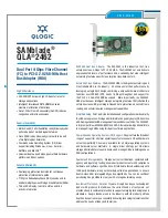
SANblade QLA 2462
Brand: Qlogic Pages: 2

DSU-09M
Brand: Axial Pages: 6

ACT-IR2000UL
Brand: ACTiSYS Pages: 20

CA12CD
Brand: Plantronics Pages: 12

WLPPO1
Brand: Wyze Pages: 4

DD10K
Brand: Yealink Pages: 32

28
Brand: Eskridge Pages: 4

JS18 Professional
Brand: Weego Pages: 16

EKS FSA Series
Brand: EUCHNER Pages: 34

NORDMARKE
Brand: IKEA Pages: 152

EC-UR4-F
Brand: Parker Pages: 2


