Vivax Metrotech vLoc3-5000, User Handbook Manual
The Vivax Metrotech vLoc3-5000 User Handbook Manual is an essential resource for users seeking detailed instructions and insights into this advanced locating system. Download this comprehensive manual for free from our website to make the most of your vLoc3-5000 and unlock its full potential.
Share
Download


Reviews:
No comments
Related manuals for vLoc3-5000

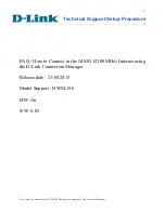
Rangebooster G WNA-2330
Brand: D-Link Pages: 2

Powerline DHP-300
Brand: D-Link Pages: 12

Powerline AV+ DHP-309AV
Brand: D-Link Pages: 2

Powerline AV+ DHP-309AV
Brand: D-Link Pages: 3

DWL-P200
Brand: D-Link Pages: 2

DWL-P100
Brand: D-Link Pages: 8

PersonalAir DBT-120
Brand: D-Link Pages: 8

Express EtherNetwork DNS-120
Brand: D-Link Pages: 16

DWA-645
Brand: D-Link Pages: 16

DWA-110
Brand: D-Link Pages: 5
DWM-156
Brand: D-Link Pages: 21

WDA-2320 RangeBooster G
Brand: D-Link Pages: 16

WDA-1320
Brand: D-Link Pages: 16

PowerLine DHP-500AV
Brand: D-Link Pages: 22

DWL-AG132
Brand: D-Link Pages: 2

DWA-548
Brand: D-Link Pages: 3

PCMCIA WIRELESS ASAPTER DWL-650
Brand: D-Link Pages: 12

Rangebooster G WNA-2330
Brand: D-Link Pages: 16


