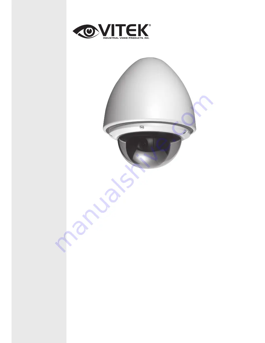
background image

VITEK

VT-PTZ40WH

960H Xpress Dome with 40X 

Optical Zoom and Advanced WDR

• 1/2.9” Sony® CMOS
• 2.1 MegaPixel With full 1080p/720p Output 
• Up to 30fps live view@ 1920x1080 (1080p)
• MegaPixel IR Corrected 9-22mm Varifocal Lens
• Mechanical IR Cut Filter (True Day/Night)
• H.264/MJPEG Dual Streaming
• 16:9 Video format
• On-board Intelligence (OBI Technology) delivers Auto-Focus-Zoom by tracking 

motion, then optically zooming in to that area of the frame

• 6 High Power 850nm IR LEDs with up to 300’ IR range
• Fully programmable advanced WDR
• Onvif Compliance
• Integrated Cooling Fan
• Standard SD memory card slot for Local recording
• Advanced OSD Functions: Motion Activated Pointing Zoom, Defog, Dynamic IR, 

BLC/HLC,  Motion Deblur, Pixel Defect Compensation, Title Set, Mirror, Flip

• Heavy Duty IP68 rated weather/vandal resistant aluminum construction
• 12VDC / 24VAC & PoE (Power over Ethernet) Operation

Specifications & installation procedure subject to change without notice.

Visit www.vitekcctv.com for the most current information available. 

Summary of Contents for VT-PTZ40WH

Page 1: ...ming in to that area of the frame 6 High Power 850nm IR LEDs with up to 300 IR range Fully programmable advanced WDR Onvif Compliance Integrated Cooling Fan Standard SD memory card slot for Local recording Advanced OSD Functions Motion Activated Pointing Zoom Defog Dynamic IR BLC HLC Motion Deblur Pixel Defect Compensation Title Set Mirror Flip Heavy Duty IP68 rated weather vandal resistant alumin...

Page 2: ...ardware and software described herein at any time without prior notice No part of this guide may be reproduced transmitted transcribed stored in a retrieval system or translated into any language in any form by any means without prior written permission of Vitek Vitek makes no warranties for damages resulting from corrupted or lost data due to a mistaken operation or malfunction of the Speed Dome ...

Page 3: ...with arrowhead symbol within an equilateral triangle is intended to alert the user to the presence of uninsulated dangerous voltage within the product s enclosure that may be of sufficient magnitude to constitute a risk of electric shock to persons The exclamation point within an equilateral triangle is intended to alert the user to the presence of important operating and maintenance servicing ins...

Page 4: ...NUAL MAY CAUSE HARMFUL INTERFERENCE TO RADIO COMMUNICATIONS OPERATION OF THIS EQUIPMENT IN A RESIDENTIAL AREA IS LIKELY TO CAUSE HARMFUL INTERFERENCE IN WHICH CASE THE USER WILL BE REQUIRED TO CORRECT THE INTERFERENCE AT HIS OWN EXPENSE CAUTION CHANGES OR MODIFICATIONS NOT EXPRESSLY APPROVED BY THE PARTY RESPONSIBLE FOR COMPLIANCE COULD VOID THE USER S AUTHORITY TO OPERATE THE EQUIPMENT THIS CLASS...

Page 5: ... of the obsolete outlet 9 Protect the power cord from being walked on or pinched particularly at plugs convenience receptacles and the point where they exit from the equipment 10 Only use attachments accessories specified by the manufacturer 11 Unplug this equipment during lightning storms or when unused for long periods of time 12 Refer all servicing to qualified service personnel Servicing is re...

Page 6: ...____________________________18 Connections__________________________________________________________19 Mounting the Dome Camera_____________________________________________20 Power on and Boot up Sequence_________________________________________21 PROGRAM OPERATION_________________________________________________22 Dome Camera Selection________________________________________________22 1 FUNCTIONS...

Page 7: ... Data___________________________________________51 6 3 Backup Data_____________________________________________________51 6 4 Restore Data____________________________________________________52 6 5 Clear Data______________________________________________________52 7 SETUP____________________________________________________________53 7 1 Preset Freeze_________________________________________________...

Page 8: ...ake sure that the following items are included in the box 1 One Xpress Dome Camera 2 One Instruction Manual 3 Three Mounting Screws 4 Three Plastic Anchors 5 Two Eight Pin Cable Assemblies If any of these materials are missing please contact the vendor or Vitek customer help desk immediately ...

Page 9: ...l 4 2 WB white balance MENU Camera WB Control 4 3 AE CONTROL MENU Camera AE Control 4 4 NIGHT SHOT MENU Camera Night Shot 4 5 CAMERA DEFAULT MENU Camera Camera Default 5 DATE TIME SETUP 5 1 EDIT DAYLIGHT SAVINGS MENU Date Time Setup Edit Daylight Savings 5 2 EDIT HOLIDAYS MENU Date Time Setup Edit Holidays 5 3 LIST HOLIDAYS MENU Date Time Setup List Holidays 6 DATA 6 1 FACTORY DEFAULT MENU Data Fa...

Page 10: ...tles 64 steps of variable speed from 0 1 sec to 420 sec Max manual speed 420 sec with Turbo key pressed Preset speed is 420 sec Programmable user preferences of speed Slow Medium Fast and AUTO Addressable up to 999 camera IDs Extendable up to 3999 in special mode Built in RS 485 receiver driver On site software upgrade and upload download of programmed data into the KBD Dome Built in power line su...

Page 11: ...joystick controllers and a variety of external switching devices such as multiplexers MUXes and Digital Video Recorders DVRs may be incorporated to accommodate the needs from a small to a large surveillance security system Figure 1 illustrates sample installation Figure 1 Typical System Configuration ...

Page 12: ...VT PTZ Series 11 INSTALLATION AND CONFIGURATION Basic configuration of speed dome camera system Figure 2 Basic Installation Diagram ...

Page 13: ... the RS485 conductor wire from the Speed Dome Camera Connect the into the Tx Tx ports of the DVR Tx Tx ports can be found in the rear part of the DVR 22AWG shield twisted pair is recommended Figure 3 Camera into DVR Connecting the Speed Dome into the Controller via j box Figure 4 Camera into Controller ...

Page 14: ...VT PTZ Series 13 INSTALLATION AND CONFIGURATION Connecting both Speed Dome and DVR via J BOX Figure 5 Connecting Camera DVR into Controller ...

Page 15: ...e set up properly before starting the installation This involves properly setting configuration switches Figure 6 shows the location of these switches Figure 6 Layout of Switches Setting the Video System Select Video system NTSC PAL and Analog or Web Dome if Web Dome is selected user should check if purchased model is supported Figure 7 Setting the Video System SW2 1 2 3 4 NTSC ON X X X PAL OFF X ...

Page 16: ...event potential control signal errors See Figure 10 for termination switch settings and examples of devices requiring termination Note Total length of the cable for communication should not exceed 1 2Km or 74 mile Figure 9 Setting Dome Camera Termination Unless there is a communication error set switches 3 4 of S4 to OFF state Position 3 4 should be set as a pair Both 3 4 to ON position or OFF pos...

Page 17: ...VT PTZ Series 16 INSTALLATION AND CONFIGURATION Figure 10 Termination Diagram ...

Page 18: ... Cam Port 16 Dome ID 16 If more than 16 dome cameras are installed using two or more DVRs the following formula is useful to determine the Dome ID ID 16x n 1 m where n number of DVR m Camera Port Refer to Figures 11 for setting the dome camera address ID and protocol selection Figure 11 Setting Dome Camera Address ID and Protocol Setting installation environment According to the installation envir...

Page 19: ...ecommended Speed Dome Controller DIP S W FUNCTION S5 Protocol S5 D1 Protocol D1 D2 D3 D4 D2 Off Off Off Off AUTO No Parity D3 On Off Off Off AUTO Even Parity D4 Off On Off Off PP S6 D1 Extend ID On On Off Off EZ D2 Baud rate Off Off On Off S2 D3 On Off On Off PD D4 Off On On Off VC On On On Off SN Off Off Off On DC Off On Off On PS On Off On On VL Off On On On DI On On On On Factory Reset S6 Baud ...

Page 20: ...g Video output Figure 2 Basic installation diagram Connecting Alarms AL1 to 8 Alarm In Magnetic PIR or other external sensor devices can be used to signal the dome camera reacting to an event See Chapter Program and Operation for configuring alarm input GND Ground NOTE All the connectors marked GND are common Connect the ground of the Alarm input and or alarm output to the GND connector NO NC Norm...

Page 21: ...Dome camera is designed to mount on a structural body supporting loads up to 11lbs 5 Kg See Figure 14 Figure 14 Example of a ceiling mounted installation Installation Hints Grab the dome head with hand as the picture above 1 Align one of hook and guide rail than makes opposite hook fit 2 Then 20 pin connector will be fitted automatically 3 Secure the lock screw on the right hook immediately ...

Page 22: ... the boot up sequence When boot up is done the following information is displayed on the monitor screen On Screen Display in normal control mode 00 00 0000 00 00 00 AM 001PRESET W ACTION1 EMPTY DATA ALARM 1 area title 360 0 090 0 3 2x CAM xxxx Preset No Information Alarm Display Pan Tilt Angle zoom Mag Action Title XPRESS DOME 2700 ...

Page 23: ...ill select dome camera 16 The selected dome camera ID will be displayed on the monitor Principle of joystick usage in the programming editing mode Button or Joystick movement in menu Function Joystick left or right Go into the sub menu items Execute the command exit Change value Navigate through the menu items Joystick up or down Navigate through the menu items Zoom handle twist Change value Incre...

Page 24: ...NU Functions By pressing the MENU button on the keyboard controller the following On screen MAIN MENU will be shown on the monitor screen Select the Functions ICON and then twist the Joystick CCW CW counterclockwise clockwise to access Functions menu ...

Page 25: ...g Dome ID and CAM 2 Press MENU to display the main menu on the monitor 3 Twist the Joystick CCW CW on Functions 4 Enter Home Function menu by twisting the Joystick CCW CW 5 Moving the Joystick to the right left or twist CCW CW to scroll Tour Pattern and Auto Scan and Preset functions 6 Select Function Number by pulling the Joystick down and twist the Joystick CCW CW The executable function number ...

Page 26: ...ter Variable Shutter Speed Auto Iris and Gain Iris Variable Iris Auto Gain and Shutter speed Bright Variable Iris and Gain This function may not be available according to the model Follow the steps below to program the Preset positions 1 On keyboard Select the camera number by pressing 0 9 and CAM 2 Press PRST button to enter preset menu MENU Functions Preset 3 Select the empty preset location to ...

Page 27: ...o the right at the Save and Exit field to finish title edit menu 11 Position the cursor on Previous Next item to select the previous next page of presets scroll through the page by moving the Joystick to the Left on Previous Next 12 Repeat steps 2 through 11 for each additional preset position 13 Select Save and Exit by moving the Joystick to the right Press ESC to exit the Preset menu without sav...

Page 28: ...up Area Screen When the position is AREA Twist joystick CCW CW and you can set the motion detection area in the area setup 1 Move the pointer to the desired position using the joystick 2 Twist the Joystick CCW CW to be active or not Or Move the pointer to the desired position using the joystick Press and hold Iris Open then move the Joystick to mark area Stop the Joystick at the desired position a...

Page 29: ... start position KEEP the camera keeps tracking mode STOP the camera stops tracking mode Target Size select the object size on the screen Large Medium Small The object size is adjusted automatically during tracking Pan Angle Limit pan angle of tracking No limit 5 180 degrees Tilt Angle Limit tilt angle of tracking No limit 5 180 degrees SHORTCUT TO PROGRAMMING PRESETS Select direction of the camera...

Page 30: ...irectly Or MENU Functions Scan 2 Select an Auto Scan number by moving the Joystick left or right 3 Twist the Joystick to edit the title in edit title menu To change name refer to section 1 2 6 4 When finish entering the title highlight START with the Joystick and twist CCW or CW Current panning position will be displayed Select start potion then Press Focus button to complete the selection of the ...

Page 31: ... or MENU Functions Tour Shortcut TOUR There are 8 programmable Tours Each Tour consists of up to 8 Preset positions Patterns Scans or other Tours Using second level Tours it can be expanded up to 56 functions in a single Tour However tours in the second level Tour will be ignored when called by the first level Tour This can be best illustrated by the following example If Tour 01 Preset 02 Preset 0...

Page 32: ...position mark will be displayed You can overwrite the programmed position 6 Repeat Step 2 through 4 for each desired position Each title will be displayed on top of the line 7 Up to 8 Presets Tours Patterns Scans can be selected for a Tour You can expand the Tour sequence by calling other programmed tours Moving the Joystick handle to right or left while the cursor is on the top of the line TOUR 0...

Page 33: ...ttern movement will automatically start recording until the focus button is pressed This procedure can be repeated to reprogram the pattern 4 Scroll down to the Save and Exit option and move the Joystick to the right to save and exit 5 Move to the title field to edit enter the name Rotate the handle CCW CW or press Tele or Wide button to enter the Edit title menu Refer to section 1 2 6 to change n...

Page 34: ...n presets scan or tour number to be called by alarm Priority 1 8 calls Preset xxx Priority 0 supports dedicated functions like a Pattern Pxx Tour Txx Scan Sxx PRI Lower No has higher priority Equal priority alarms will be serviced repeatedly IN NO NC normally Open Closed OFF ignore OUT R01 Relay out 1 R02 Relay out 2 OFF No output HLD Alarm will be held for programmed time 01 to 255 seconds LATCH ...

Page 35: ... Preset Status of Input NC NO OFF and Output R01 R02 OFF by moving the Joystick to the right or to the left 4 To increase or decrease the preset number or to change the status or output number twist the Joystick CCW CW In case of preset programmed preset number will be scrolled 5 Position the cursor on Save and exit and moving the Joystick to the Save and exit Press ESC to exit the program without...

Page 36: ...gram a function at a specific date and time Action Number up to 99 Function Type Preset Scan Pattern Tour Auto Pan D N COLOR D N B W D N AUTO Alarm Out Alarm In Function Number 001 248 for preset Function Status ON OFF Alarm Out only Action Active Yes No Action Title up to 12 characters refer to the title of the preset Action Day On H Holiday S Sunday M Monday T Tuesday W Wednesday T Thursday F Fr...

Page 37: ...Joystick left or right and twisting the ZOOM handle 7 Select Add Action to List and move the Joystick left or right Then the stored action number displays 8 To add other action number repeat step 1 to 7 Edit the stored action 1 Select the desired action number by moving the Joystick left or right or twisting the ZOOM handle at the action number field 2 Change each option as procedures above 3 Sele...

Page 38: ...cur on a day if that date is in the list of holidays Off The action only occurs on a day of the week that it is set Holidays have no effect on the action SUNDAY SATURDAY On The action will occur on a day of the week for which it is set Off The action will not occur on a day of the week ALL ON Set all days to On for your convenience ALL OFF Set all days to Off for your convenience 1 Select the desi...

Page 39: ...Auto Pan Day Night Alarm Out Alarm In 1 Select the list action by moving the Joystick up or down 2 Twists the ZOOM handle to select function type at the list action field 3 Push the Joystick right to sort the list according to the selected action type 4 Push the Joystick right or left at the Previous Next to see the next numbers ...

Page 40: ... the monitor screen Highlight Screen and then twist the Joystick CCW CW to enter Screen menu 3 1 LANGUAGE SETUP MENU Screen Language Moving the joystick handle to the right to select Language options Preferred language can be scrolled by moving the joystick to the right on Language Currently only English language but future firmware will include more languages ...

Page 41: ...er position by moving the Joystick to the right To finish entering the title move the Joystick down to Save and Exit then twist 4 Privacy zone blocking Method you can select the style of privacy by highlighting Method and selecting MOSA Video off block default or none privacy turned off 5 To delete the masked zone move the Joystick and highlight zone you want to delete Press the Home or Off Button...

Page 42: ...racters by rotating the handle Move to the next character by moving the Joystick to the right To finish entering the title move the Joystick down to Save and exit and twist 4 To adjust panning limit highlight Start or End and twist joystick Then use the Joystick to set the desired direction The end limit must be in an increasing direction Start End press the Focus button to save and exit from cont...

Page 43: ...ngs are available for each label except alarm OFF Label is not displayed when activated ON The label is continuously displayed when activated 2 5 10 SEC is displayed for the selected seconds after activation The alarm and date time options are On and Off only North Direction ON OFF ON sets current direction as N north and the coordinate angle to 000 OFF hides the directional title Every 90 degrees...

Page 44: ...ore edges in the picture will be enhanced TYPE A 0 15 TYPE B 0 63 AUTO Digital Zoom OFF Zoom range is limited to the optical 2x Zoom is extended up to 2x of digital range 4x Zoom is extended up to 4x of digital range MAX Zoom is extended Max digital zoom range Defog When the surrounding area of the subject is foggy and low contrast the defog mode will make the subject appear clearer by emphasizing...

Page 45: ...ent condition This will shorten the lifespan of the lens 4 2 WB white balance MENU Camera WB Control Mode AUTO INDOOR OUTDOOR ONE PUSH ATW MANUAL MANUAL Control of R and B gain AUTO Computes the white balance value output using color information from the entire screen automatically 3000 to 7500 K INDOOR 3200 K base mode OUTDOOR 5800 K base mode ONE PUSH One push white balance mode is a fixed WB mo...

Page 46: ...nd Gain Slow Shutter ON OFF AUTO mode only Iris CLOSE F28 F22 F19 F16 F14 F11 F9 6 F8 0 F6 8 F5 6 F4 8 F4 0 F3 4 F2 8 F2 4 F2 0 F1 6 40X MODEL Gain 0 2 4 6 28 3 DB Bright 0 1 2 3 4 29 30 31 Shutter 1 1 1 2 1 4 3 1 8 6 1 4000 3500 1 6000 1 10000 Bright Offset Adjust the brightness level 7 0 default 7 AUTO SHUTTER IRIS mode only WDR Wide Dynamic Range Mode OFF ON AUTO DNR Digital Noise Reduction OFF...

Page 47: ... the selected camera is set to Manual 10 ON will enable the Night Shot mode 10 OFF will turn off the Night Shot mode Mode MANUAL AUTO AUTO Camera automatically goes into B W mode at low light MANUAL Manually controls the Night Shot mode in LOCAL CONTROL option On Off Night shot mode remotely by pressing 10 ON 10 OFF 4 5 CAMERA DEFAULT MENU Camera Camera Default Returns all changed camera values to...

Page 48: ...e When installing the dome for the first time the clock will not operate until date and time are set The date and time can be displayed on the monitor when the Date Time option is set to ON in the display menu 5 1 EDIT DAYLIGHT SAVINGS MENU Time Date Edit Daylight Savings ...

Page 49: ... year Relative The holiday occurs on a different date each year such as the fourth Thursday in November 3 Select the month week relative type only and day 4 Select Add Holiday and twist or tap the Joystick to right 5 Select YES and push the Joystick to right 6 Repeat step 1 5 to create other holidays 7 Select Exit and push the Joystick to the right Use the following steps to edit a holiday 1 Selec...

Page 50: ...ystick to right then the next number displays at the number field If no number added NEW displays at the number field 4 Repeat step 1 3 5 Select Exit and push the Joystick to the right 5 3 List Holidays MENU Time Date List Holidays List Holiday ALL Each Month 1 Select the list type by twisting the Joystick and push the Joystick right 2 Push the Joystick right or left at the Previous Next to see th...

Page 51: ...ROGRAM OPERATION 6 DATA SETUP MENU Data Setup 6 1 FACTORY DEFAULT MENU Data Setup Factory Default The factory default returns programmed data to initial state as ex factory except the followings Time and date Alarm list ...

Page 52: ...u want to erase 2 Twist the Joystick CCW CW on ERASE CAUTION Unless you download the data into a safe place all the data in the selected dome camera will be lost Refer to Download Upload data function in the Keyboard Configuration utility 6 3 BACKUP DATA MENU Data Setup Backup Data This function stores the setting values of the dome into backup memory Note when the connector board has no memory th...

Page 53: ...TION 6 4 RESTORE DATA MENU Data Setup Restore Data This function restores the setting values of the dome from the backup memory to the dome 6 5 CLEAR DATA MENU Data Setup Clear Data This function clears all data of the backup memory ...

Page 54: ...ozen during calling preset 7 2 SPEED MENU Setup Speed User can select preferable speed of manual control SLOW MEDIUM FAST 7 3 RESPONSE MENU Setup Response ON Dome sends answer packet after receiving command packet OFF Dome doesn t send answer packet after receiving command packet 7 4 DOME ANGLE MENU Setup Dome Angle ...

Page 55: ...era ON When the camera reaches the moving object directly below the dome the dome Camera tracks the object smoothly with a digitally corrected image OFF The dome camera does not perform a flip 7 4 2 PANNING RANGE MENU Setup Dome Angle Pan Range When the dome camera is installed near a wall or on a corner panning range can be limited by user 7 4 3 TILT OVER ANGLE MENU Setup Tilt Range ...

Page 56: ...e viewing angle is narrower and the ceiling line disappears Without Bubble The tilt range of the camera is limited to see the horizon so the picture shows part of the ceiling line With Bubble The tilt range of the camera is limited to see below the horizon 10 degrees AUTO The tilt range of the camera is limited automatically according to the zoom ratio 5 10 degrees when it moves vertically 7 5 CAL...

Page 57: ...ng the joystick up and down and then twist the joystick handle 3 To move to the next digit push the joystick to the right 4 Repeat step 2 4 up to four digits At this time the new password confirmation displays 5 Reenter password 6 If two passwords match the edit password completed If two passwords don t match the message of Password is not changed displays At this time try it again Note When the p...

Page 58: ...VT PTZ Series 57 PROGRAM OPERATION 7 7 SYSTEM INFORMATION MENU Setup System Information This screen shows information of the dome camera for service or trouble shooting EZ 2700 ...

Page 59: ... Wide Dynamic YES DeFog YES BLC Back Light Compensation ON OFF DNR Digital Noise Reduction 1 5 OFF DIS Digital Image Stabilizer ON OFF Pan Angle 360º Continuous Manual Pan Speed sec 0 1 105º sec Autoscan 420º sec Tilt Travel 5º 90º 95º Manual Tilt Speed sec 0 1 90º sec Preset Tilt Speed sec 380º sec Proportional Pan Tilt Yes Communication RS 422 485 8bit 1bit stop No Parity 2 4 230Kbps Preset 248 ...

Page 60: ...VT PTZ Series 59 TECHNICAL SPECIFICATIONS Dimension Figure 16 Dimension ...

Page 61: ...nents in the system Verify that the power switches are ON Check that the BNC connectors are securely connected Poor video quality Check the voltage level of the dome camera Check the power supply voltage nominal 24VAC Dome cameras lose their positions Reset the cameras using the Dome configuration menus Check if there is unusual sound Check the voltage level of the dome camera Camera number does n...

Page 62: ...e original buyer or end user customer of a VITEK Authorized Reseller The product must have been used only for its intended purpose and not been subjected to damage by misuse willful or accidental damage caused by excessive voltage or lightning The product must not have been tampered with in any way or the guarantee will be considered null and void This guarantee does not affect your statutory righ...

Reviews: