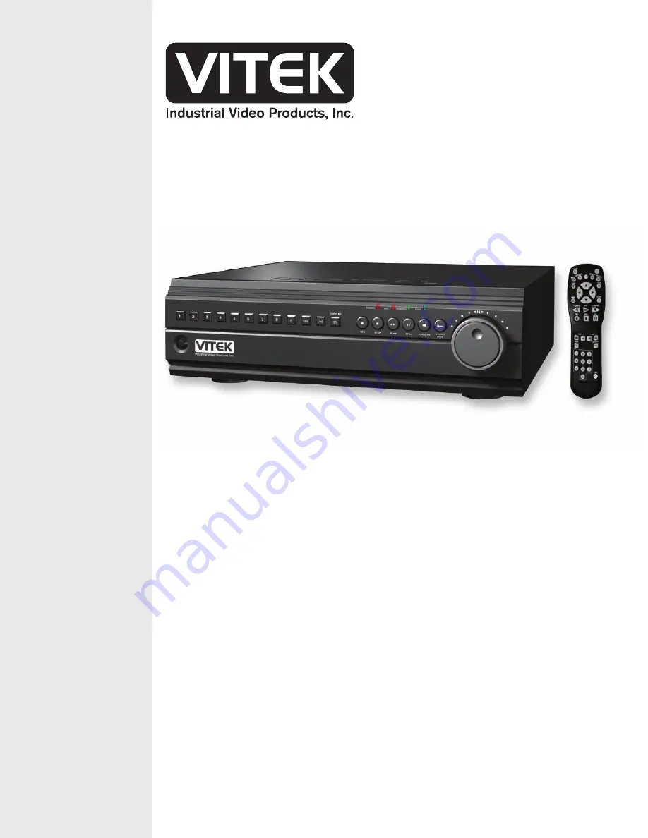
background image

VITEK

VT-DVR Series

4, 8, & 16 Channel

Digital Video Recorders

FEATURES:

• Remote Access & Management from Client PC

• Embedded Linux Operating System

• Built-in Multiplexer

• Quadplex Function

• High Resolution

• Hidden/ Covert Camera Function

• Built-in Web Server for LAN/WAN/ Internet

• Automatic E-mail Notification: External Alarm, Video Loss, Power Loss, HDD Failure

• Dedicated Multi-Site/ Enterprise Client Software or Plug-In for Internet Explorer 6.0

• External Back-up Devices(USB-2): CD-RW, DVD-RW, HDD, USB Flash Memory Stick(1.1)

• Mini Player: Auto Install when backing up files into CD or DVD

• Up to 800GB of Internal Storage

• Jog/Shuttle Operation

• IR Remote Control - Control Upto 99 DVRs

• Optional P.O.S. Interface

• Optional VGA Output 

Summary of Contents for VT-DVR

Page 1: ...N WAN Internet Automatic E mail Notification External Alarm Video Loss Power Loss HDD Failure Dedicated Multi Site Enterprise Client Software or Plug In for Internet Explorer 6 0 External Back up Devices USB 2 CD RW DVD RW HDD USB Flash Memory Stick 1 1 Mini Player Auto Install when backing up files into CD or DVD Up to 800GB of Internal Storage Jog Shuttle Operation IR Remote Control Control Upto...

Page 2: ...at the following items are included in the box 1 Digital Video Recorder 2 NVAC RC110 Remote Controller 3 DVR Client Software CD 4 Power Cable 5 Two AAA Batteries 6 This Instruction Manual If any of these materials are missing please contact the vendor or the customer help desk immediately ...

Page 3: ...o warranties for damages resulting from corrupted or lost data due to a mistaken operation or malfunction of the Digital Video Recorder the software the hard drives personal computers peripheral devices or unapproved unsupported devices Trademark Acknowledgements z DVR Web Client and DVR Local Player are trademarks of the manufacturer z DiamondMax Plus 9 DiamondMax 16 MaxLine II and MaxLine Plus I...

Page 4: ...a particular installation If this equipment does cause harmful interference to radio or television reception which can be determined by turning the equipment off and on the user is encouraged to try to correct the interference by on or more of the following measures z Reorient or relocate the receiving antenna z Increase the separation between the equipment and receiver z Connect the equipment int...

Page 5: ...ble The Privacy act of 1974 5 U S C 552a Please note that the Digital Video Recorders are intended for recording of surveillance use and should never be used in a manner that invades other people s privacy or contravenes international or domestic privacy act and its regulations Please be advised that in certain cases the recording of individuals private properties or commercial properties by means...

Page 6: ...tion may result in high voltage electrical shock Internal inspections alterations and repairs should be conducted by qualified service personnel authorized by the equipment distributor or the customer help desk z Stop operating the equipment immediately if it emits smoke or noxious fumes Failure to do so may result in fire or electrical shock Immediately turn the DVR s power off remove the power c...

Page 7: ...ies Use of power sources not expressly recommended for this equipment may lead to overheating distortion of the equipment fire electrical shock or other hazards z Do not place the battery near a heat source or expose them to direct flame or heat Neither should you immerse them in water Such exposure may damage the battery and lead to the leakage of corrosive liquids fire electrical shock explosion...

Page 8: ...arge the backup battery This procedure is necessary when using the DVR for the first time or after it has been unplugged for a long time from the power outlet Insufficient charging of the battery may cause loss of the time and date settings if the power supply should fail The battery when fully charged will store the saved settings for approximately 170 hours PREVENTING MALFUNCTIONS z Avoid Strong...

Page 9: ...OUT 13 1 FRONT PANEL LAYOUT 13 2 REAR PANEL LAYOUT 16 3 REMOTE CONTROLLER 18 4 INSTALLATION AND CONNECTION 19 5 PTZ CAMERA CONNECTION 20 USING THIS MANUAL 21 I BASIC SETTINGS 22 TIME DATE SETTING 22 SCREEN POSITION ADJUSTMENT 22 II BASIC OPERATION 23 1 MAIN SCREEN 23 2 INFORMATION LOG LIST 26 3 LIVE VIEW 28 1 LIVE VIEW SWITCH SEQUENCE 28 Live view switch sequence of 4 CHANNEL DVR 28 Live view swit...

Page 10: ...49 1 PIP SET 49 2 AUTO SEQUENCE MODE 50 3 SEQUENCE INTERVAL 50 4 CAMERA SELECT 50 CAMERA TITLE 51 SEQUENCE BYPASS 51 PTZ CHANNEL 51 PTZ CAMERA MODEL 52 BRIGHTNESS 53 CONTRAST 53 COLOR 53 COVERT MODE 54 2 GROUP SELECTION 55 1 RECORD GROUP 55 2 AUDIO INPUT 55 3 HDD OVERWRITE 56 3 RECORD SETUP 57 1 DEFINE GROUP 57 2 PICTURE QUALITY 57 3 AUDIO RECORD 58 4 FIELD RATES MOTION AND ALARM ACTIVATION 58 A F...

Page 11: ...NSTALLING THE DVR WEB CLIENT 89 INSTALLING THE DVR WEB CLIENT BY CONNECTING TO A DVR 90 INSTALLING THE DVR WEB CLIENT FROM THE PROGRAM CD 90 CONNECTING TO THE DVR USING THE WEB CLIENT 91 2 DVR WEB CLIENT 93 1 CAMERA DISPLAY SELECTION 94 2 WEB CLIENT SETTINGS 94 3 DVR SETTINGS 95 GENERAL 96 DISPLAY SETUP 96 GROUP SELECTION 97 RECORD SETUP 97 EVENT SETUP 98 SYSTEM SETUP 98 4 DOWNLOAD MANAGER 99 PREV...

Page 12: ... DOWN MENU 110 8 PICTURE QUALITY SELECTION PULL DOWN MENU 110 9 REGION SETTING PULL DOWN MENU 110 VII CENTRAL MANAGEMENT SOFTWARE 111 1 SYSTEM REQUIREMENT 111 2 INSTALLING DVRPLAYER 111 3 DVRPLAYER 113 1 MAIN CAMERA DISPLAY WINDOW 113 2 CAMERA DISPLAY SELECTION 113 3 MODE DISPLAY 113 4 TIME AND DATE 114 5 MODE SELECTOR 114 6 RECORD 114 7 CAPTURE 114 8 OSD MODE 114 9 SETUP 114 10 PLAYBACK CONTROL B...

Page 13: ...or download 134 Local Playback 135 6 CONTEXT MENU 136 Channel Context Menu 136 DVR Context Menu 137 Virtual DVR Context Menu 138 7 DVR SETUP 138 Display Setup 138 Group Selection 138 Record Setup 139 Event Setup 139 Schedule Setup 139 System Setup 140 VIII SPECIFICATION 142 IX FREQUENTLY ASKED QUESTIONS FAQ 143 X TECHNICAL SUPPORT 148 INDEX 149 ...

Page 14: ...lay modes single 4 channel 6 channel 8 channel 9 channel 13 channel and 16 channel split screen display modes 3 STATUS INDICATOR Four LEDs display the status of the Digital Video Recorder From the left Power red Recording red Scheduled Recording green and Button Lock green 4 RECORD This button starts recording 5 STOP This button stops recording 6 PLAY REVERSE PLAY This button is used to start the ...

Page 15: ...is feature is activated To unlock press the lock button again and enter the password when prompted 13 ZOOM This button allows to digitally zoom into a specific area in both live and playback screen Press the button to display the zoom area box use the arrow keys to move the box then press zoom button again to enlarge the selected area 14 RESTORE This feature is no longer supported 15 BACKUP This b...

Page 16: ...n changes in submenus In Zoom mode pressing this button will exit to the original display screen In the regular display screen this button is used to hide the On Screen Display information such as time date and channel icons This button also removes any of the alert icons on the upper right corner of the screen AL VL and PL This button is also used to turn off the alarm buzzer 24 TIME SEARCH This ...

Page 17: ...VITEK VT DVR Series 16 2 REAR PANEL LAYOUT 4 CHANNEL DVR 8 CHANNEL DVR 16 CHANNEL DVR 1 2 3 6 9 7 10 4 5 8 11 12 13 14 15 1 2 3 6 9 7 10 4 5 8 11 12 13 14 15 1 6 9 7 10 4 5 8 11 12 13 14 15 ...

Page 18: ...k connector 5 AUDIO INPUT RCA jack connector 6 MIC INPUT 1 8 Microphone Jack 7 ALARM SIGNAL INPUTS OUTPUT 8 USB 2 0 PORT External backup devices CD RW DVD RW and external hard drive 9 RJ45 ETHERNET PORT 10 100Base T RJ45 Ethernet Port for network connection 10 RS 232C 9 Pin port connector to connect an external modem or RS 232C RS 485 converter 11 S VIDEO OUTPUT 12 COMPOSITE VIDEO OUTPUT BNC conne...

Page 19: ...LLER REWIND PLAY POWER PAN TILT ZOOM BACK UP DVR ID MENU RESTORE RECORDING STOP FAST FORWARD DISPLAY MODE LOG INFORMATION AUDIO PB SCHEDULE REC ON OFF TIME SEARCH ENTER CH SELECT ZOOM FIELD BY FIELD CANCEL OSD OFF ALARM SEARCH NUMBERS ALPHABET ...

Page 20: ...VITEK VT DVR Series 19 4 INSTALLATION AND CONNECTION ϖ Example of a normally open alarm circuit ...

Page 21: ...RA CAM1 CAM2 CAM3 CAM4 CONTROL LINE CAM5 CAM6 CAM7 CAM8 CAMERA IN 1 2 3 4 5 6 7 8 9 10 11 ETHERNET 13 14 15 16 COMPOSITE S VIDEO VIDEO OUT AUDIO MIC OUT IN USB RS 232C 12 A1 A2 A3 A4 G A5 A6 A7 A8 G A9 A10 A11 A12 G A13 A14 A15 A16 G AO G 100V 230V AC IN RS 232c to RS 485 Converter ...

Page 22: ...ight Use the directional buttons to navigate up or down between item selection Use the directional buttons to navigate left or right between item selections Use the directional buttons to modify the values of submenus Use the numeric buttons to enter the values or to switch between channels Use 10 button in combination with single digit buttons to enter or channels higher than 10 Use the menu or e...

Page 23: ...rmat and date using the numeric buttons Press the Menu Button to save and exit The password prompt will appear as soon as the time and date has been entered Enter 000000 as the default password Screen Position Adjustment The screen position is adjustable during live view or playback Use the directional buttons to adjust the screen position to best fit the monitor Default Position Up position botto...

Page 24: ...ter Moreover it will also address several live view modes the DVR has to offer which include several multiple channel view modes automatic sequence modes and the channel swapping feature as well as the zoom feature Finally this section will also include the information screen where all the basic information about the DVR is displayed as well as the log screen where all the activities of the DVR ar...

Page 25: ...e record button is pressed and continuously while the DVR is in recording mode 6 POWER LOSS ALERT Displayed when there was an interruption in the power supply The power loss warning icon is displayed after the power comes back on If an e mail address was entered under the network setup menu an e mail will be sent when the DVR is powered on again 7 CHANNEL ICONS Displays the current status of each ...

Page 26: ... the remaining time until the next overwrite The remaining time may fluctuate based on the amount of information that changes per camera while recording 13 REMAINING HARD DRIVE SPACE Displays the remaining hard drive storage space in gigabytes If the hard drive overwrite is set to on the counter will remain as 0 and the DVR will continue to write on to the hard drive from the beginning The counter...

Page 27: ...uch as CD RW DVD RW or external hard drives attached to the DVR USB VENDOR Displays the USB backup device s manufacturer USB DISK SIZE Displays the remaining and the maximum capacity of the external hard drive when attached to the DVR HDD SIZE Displays the remaining and the maximum capacity of the internal hard drive s SYSTEM VERSION Displays the DVR s system version FIRMWARE VERSION Displays the ...

Page 28: ...nce more or exit out to the main screen by pressing the menu button then press the log button to access the DVR s log chart The log chart keeps record of up to 255 pages of all the events and alerts totaling 2395 logs The events are recorded from the initial power on of the DVR The record of items compiled along with the date and the time of its occurrence are shown as follow z Menu Set z Play z R...

Page 29: ...second for the 16 CHANNEL DVR 1 LIVE VIEW SWITCH SEQUENCE The 4 CHANNEL DVR only has the quad view mode and the PIP view mode whereas the 8 CHANNEL DVR and the 16 CHANNEL DVR have quad 6 8 9 8 channels only on 8 CHANNEL DVR 13 16 CHANNEL DVR and 16 channel view 16 CHANNEL DVR The following illustrations display the order of live view mode sequence Live view sequence of 4 CHANNEL DVR Live view sequ...

Page 30: ...VITEK VT DVR Series 29 Live view sequence of 16 CHANNEL DVR ...

Page 31: ...be displayed one after another If the 4 channel view mode is selected then it will maintain the format in sequence 3 CHANNEL SELECT REPOSITIONING On 6 8 and 13 channel view mode 6 and 8 channel view mode only on 8 CHANNEL DVR it is possible to reposition the camera from the bigger window with the one from a smaller one The following illustration demonstrates the procedure From 6 8 or 13 channel vi...

Page 32: ...d with camera 1 The switching function of cameras also applies during the playback 4 ZOOM During live view mode or during the playback it is possible to zoom into a section of the screen to get a close up view of the screen Press the zoom button to bring up the zoom window Use the directional buttons to move the zoom window to the desired location ...

Page 33: ...Series 32 Press the zoom button once more to zoom into the selected area on the screen Use the directional buttons to move the zoomed window around the screen Press the cancel OSD off button to return to normal view ...

Page 34: ...y Fi el ds PerSecond perchannel Audi o Recor d Gr oup 1 Super 15 of f Gr oup 2 Super 15 of f Gr oup 3 Super 15 of f Gr oup 4 Super 15 of f 8 CHANNEL DVR Recor d Gr oup Pi ct ur e Qual i t y Fi el ds PerSecond perchannel Audi o Recor d Gr oup 1 Super 7 of f Gr oup 2 Super 7 of f Gr oup 3 Super 7 of f Gr oup 4 Super 7 of f 16 CHANNEL DVR Recor d Gr oup Pi ct ur e Qual i t y Fi el ds PerSecond percha...

Page 35: ...t the playback from the earliest recorded data During the playback the DVR may be played back in reverse paused speed search up to 16 times normal speed or move field by field using the jog shuttle Please refer to the following illustrations for a detailed description Press the play button and the play icon will be displayed The DVR will start the playback from the earliest data Press the play but...

Page 36: ...eld or to fast forward or to fast rewind to desired location During the playback or in still mode turn the jog dial clockwise or the step buttons on the remote controller to enter the field by field mode and to advance and view recorded data one field at a time If the jog dial is stopped the playback will return to still mode Turn the jog dial or the step buttons on the remote controller counter c...

Page 37: ...n the shuttle ring counter clockwise or the fast reverse button on the remote controller to fast reverse to the desired location The same speed increment and icon concept is applied for the fast reverse Releasing the shuttle ring will bring the fast forward to still mode The diagram to the left represents the shuttle ring and the increments that represent each fast forward or fast reverse speed 16...

Page 38: ...s always recorded in real time unlike the video data that can be recorded in various modes including real time There may be a slight delay in synchronization of the audio to video During the playback press the audio PB button to synchronize the audio to video as closely as possible The audio cannot be played back in the multi screen view The single channel view must be selected to play back the au...

Page 39: ... on the DVR or the remote controller will have no effect To unlock the buttons press the lock button once more then enter the administrator s password to clear the button lock status The lock LED will be turned off 2 BACKUP When a CD RW DVD RW or an external hard drive is connected through the USB port the backup icon will pop up as shown to the left There are two methods of backing up the content...

Page 40: ... that the end time does not precede the start time An arrow will appear to the left of the backup icon as the icon s wheel will start spinning signifying that the backup is in session If there is not enough space on the media the DVR will automatically eject the disk when it s full then will resume the process once a new media is inserted into the drive When finished the wheel will stop spinning a...

Page 41: ...lly copy the data from the internal hard drives to the external hard drives The DVR will start backing up the oldest data first up until the latest file then will continue to backup onto the external hard drive in real time as the DVR continues to write the data onto its internal hard drive 3 USB 2 0 MEMORY STICK The ease of portability and versatility of alternate storage medium USB 2 0 compliant...

Page 42: ...ause the playback at the desired time or the event Pause the playback and then press Backup SNAP SHOT will be displayed and the current screen will be saved onto the memory stick as picture format file The files can be retrieved and displayed using the Local Player in snapshot folder ...

Page 43: ...in the PTZ control menu can only be accessed using the fast forward and fast rewind button on the remote controller Please have the remote controller handy when using the PTZ camera 1 PAN AND TILT CONTROL Use the directional buttons to pan and tilt the PTZ camera The directional buttons will remain as the basic pan and tilt controller for all pages On the remote controller use the diagonal directi...

Page 44: ...MATIC PAN TILT ZOOM CONTROL a Automatic PTZ control offers basic automatic pan tilt or pan and tilt for the PTZ cameras It is also possible to customize the PTZ path as well as the focus zoom and iris of the PTZ camera All of these features can be stored as a preset Use the step buttons on the remote controller to navigate through the selections Auto Pan Auto Tilt and Auto P Tilt are activated by ...

Page 45: ...umber will start flashing Using the directional button select the number that corresponds to the preset number to move the PTZ camera to preset positions Once all PTZ camera positions have been confirmed move the arrow to tour and then press the P T Z Focus button to start the automatic PTZ camera tour Press the cancel OSD off button to stop the automatic PTZ camera tour 6 LIMITING THE CAMERA POSI...

Page 46: ... set to the standby mode until an alarm is triggered The DVR is not recording as long as the record LED is blinking When an alarm is triggered the record LED will turn solid The alarm alert and the alarm recording icons will appear on the screen The DVR will record for the duration of the post recording duration If the alarm buzzer is set to on then the alarm buzzer will sound for the duration of ...

Page 47: ...grid setting may be ignored Press the record button and the record icon will appear as shown on the left The record LED will start blinking as it is set to the standby mode until motion detection is triggered The DVR is not recording as long as the record LED is blinking When a motion is detected the record LED will turn solid The motion recording icon will appear on the screen and the DVR will re...

Page 48: ...nd minute slot Press the time search button to start the playback The DVR will initially start to play all recorded channels simultaneously 2 EVENT SEARCH Press the alarm search button to access the alarm search menu Use the directional buttons to navigate to the desired event and between the pages The events are listed in chronological order starting with the most recent event Press the alarm sea...

Page 49: ...VITEK VT DVR Series 48 IV ADVANCED SETTINGS Press the menu button to access the main menu for the advanced settings of the DVR The menu will display the following categories ...

Page 50: ...nly on the 4 CHANNEL DVR the Picture in Picture function enables the display of secondary channel of choice in a smaller window while viewing one channel of choice in full screen mode Use the Display button to switch between the 4 channel mode and PIP mode a Main Display Select the Channel to display in the background b PIP Display Select the channel to display in the foreground c PIP Size Select ...

Page 51: ...annel view or the quad channel view is selected Press the Display button to switch to any other channel view modes to stop the automatic sequence mode 3 SEQUENCE INTERVAL This option selects the amount of seconds each channel all models or each 4 channel mode 8 CHANNEL DVR and 16 CHANNEL DVR is displayed The default setting is one second The interval can be increased up to five seconds 4 CAMERA SE...

Page 52: ...etters and numbers Refer to the following illustration for the sequence of alphabets and numbers 1 2 A B C 3 D E F 4 G H I 5 J K L 6 M N O 7 P Q R 8 S T U 9 V W X 0 10 Y Z b SEQUENCE BYPASS Sequence bypass allows the cameras to be included or excluded from the automatic sequence display By default sequence by pass is off for all cameras c PTZ CHANNEL Select the appropriate channel for the PTZ Came...

Page 53: ... HONEYWELL GC 655 N P 9600 1 0 0 10 SUNKWANG WPT 101 9600 1 0 0 11 PELCO D PROTOCOL 2400 1 0 0 12 PELCO D PROTOCOL 4800 1 0 0 13 PELCO D PROTOCOL 9600 1 0 0 14 15 CANON VC C4 9600 1 0 0 16 PELCO PROTOCOL 2400 1 0 0 17 PELCO PROTOCOL 4800 1 0 0 18 PELCO PROTOCOL 9600 1 0 0 19 PELCO Extended 2400 1 0 0 20 PELCO Extended 4800 1 0 0 21 PELCO Extended 9600 1 0 0 22 Panasonic WV CS85x WV CS86x 9600 1 0 ...

Page 54: ... previous menu f CONTRAST Highlight Contrast then press the right directional button to access the contrast adjustment screen Adjust the contrast using the left or the right button then press menu to save and exit to previous menu g COLOR Highlight Color then press the right directional button to access the color adjustment screen Adjust the color using the left or the right button then press menu...

Page 55: ... 54 h COVERT MODE Select between covert mode on and normal mode off If covert mode is activated the activated camera s display will be hidden on both the monitor and the DVR web client yet the video will still be recorded ...

Page 56: ...n may also be selected under group selection 1 RECORD GROUP This option selects the camera groups configured in the Record Setup which sets the fields per second and the picture quality The Default recording group is Group 1 and will change to any other groups based on the selections made here 2 AUDIO INPUT This option selects the audio input method MIC is for microphone input and LINE is for line...

Page 57: ...VITEK VT DVR Series 56 3 HDD OVERWRITE This option determines whether the DVR writes over old files when the hard drive become full By default the HDD overwrite is off ...

Page 58: ...ed and stored 1 DEFINE GROUP Define Group configures picture quality audio recording and field rate for each camera for each group It also activates and deactivates motion trigger and alarm trigger 2 PICTURE QUALITY Use the left or the right directional buttons to select from eight different picture qualities z Super 32KB z Super 28KB z High 26KB z High 21KB z Mid 18KB z Mid 15KB z Low 12KB z Low ...

Page 59: ...the field rate The maximum field rate is 30 fields per second real time recording and the slowest field rate is one field per minute Refer to the following illustration for a more detailed explanation of field distribution over cameras C am er a C am er a 1 30 15 10 7 6 4 C am er a 2 30 15 10 7 6 4 C am er a 3 X 15 10 7 6 4 C am er a 4 X 15 10 7 6 4 C am er a 5 X X 10 7 6 4 C am er a 6 X X 10 7 6 ...

Page 60: ...ctivate or deactivate the motion and the alarm features In the example to the left camera 1 s motion feature is activated Press the same numeric button once more to activate camera 1 s alarm feature Press the same numeric button once more to activate both motion and alarm features Press the same numeric button one last time to disable both the motion and alarm features ...

Page 61: ...rds after the initial motion or alarm detection The user may choose from 0 20 40 60 80 100 120 180 and 240 seconds Zero seconds continues to record until the recording is stopped manually The default duration is 60 seconds 2 PRE RECORD The DVR keeps at all times 140 fields of recording in its buffer in order to compensate for events that happened prior to the initial motion or alarm detection When...

Page 62: ... been addressed The default setting is off 4 ALARM OUT The DVR sends an electric signal when alarm is triggered to activate external devices such as speakers or other types of relays that accept electric triggers Two levels of output are available Low 0 1 volt 0 8 volt High 4 0 volt 5 0 volt The maximum output is 1 mAmp 5 VDC 5 CAMERA SELECT This option configures the motion grid to trigger the mo...

Page 63: ...buttons to adjust the sensitivity level All grids are on by default b MOTION LEVEL Use the left or the right directional buttons to adjust the motion sensitivity level Sensitivity level 1 is the lowest setting and level 15 is the highest setting The default sensitivity level is 8 c ALARM INPUT Select different types of alarm circuit type The DVR accepts both normally open circuit signals and norma...

Page 64: ...the schedule LED will blink a DAYS OF THE WEEK D W The days of the week or all days of the week may be configured by pressing the numeric buttons Refer to the following chart to select the days of the week 1 Sunday 5 Thursday 2 Monday 6 Friday 3 Tuesday 7 Saturday 4 Wednesday 8 All Days b START END Enter the starting and the ending time of the recording The time format must be in 24 hour format Th...

Page 65: ...rday and Sunday weekend from 7am on Saturday to 8am on Sunday using group 4 Note that the schedule s start and end time does not automatically move to the next day As shown in example If the schedule recording needs to continue through the night onto the next day the end time must be set to 23 59 hour 11 59pm on the first day to mark the end of the day Then set the start time to 00 00 hour 12am an...

Page 66: ...hat needs to be deleted Press the numeric button 6 to change the group to dotted bar Press the Menu button to save and exit to the main menu screen Press the right directional button to access the schedule setup once more and the selected entry will be deleted from the schedule ...

Page 67: ... value and exit to the main menu If for some reason the date and the time were entered so that it conflicts and overlaps previously entered date and time the DVR will not overwrite the older data Instead a new copy of the data with the same date and time will be created on another part of the DVR s internal storage When the user plays back the data from the hard drive the DVR will playback the old...

Page 68: ... USER AND THE ADMINISTRATOR PASSWORD The user password is the general password used for non critical features such as unlocking the buttons after the auto button lock has been activated or to connect to the DVR remotely using the DVR Web Client The user level password also grants access all the features except system power off stop recording main menu lock and schedule The administrator s password...

Page 69: ...rmed the DVR will automatically save the new password and exit to the System Setup Menu 2 FORMAT HDD Format HDD should only be used when the content of the internal storage needs to be wiped out or when the user wishes to record from scratch as new Highlight format HDD then press the right directional button to access the Disk Format screen ...

Page 70: ...played The example to the left displays 150 seconds remaining as it took 150 seconds to format previously Sometimes the internal storage cannot be formatted and the DVR will display Restart the system first prompt due to the following reasons a The DVR is currently recording or was recording prior to formatting b The DVR was playing back the recorded data When this prompt is displayed stop the rec...

Page 71: ...c mode Manual mode allows selective backup of recorded data Automatic mode backs up the entire content of the internal storage onto the external hard drive Automatic backup mode will also allow real time backup of the internal storage onto the external hard drive The default setting is manual The DVR can play back from the internal or external hard drive when an external hard drive is attached to ...

Page 72: ...turn button beep off 6 SELECT DVR ID Up to 99 DVRs can be controlled using one remote controller To select the DVR to be controlled with the remote controller press and hold the DVR ID button While holding the DVR ID button press the appropriate DVR ID number For example enter 05 for DVR ID 05 enter 43 for DVR ID 43 and such ...

Page 73: ...tinguish the two solutions according to the commonly available service type to configure the DVR for the networking purposes 1 CONFIGURING THE DVR WITH STATIC IP ADDRESS Internet service providers who offer dedicated services such as T1 SDSL Symmetric Digital Subscriber Line or equivalent services usually provide a batch of external Public static IP addresses that remain constant These IP addresse...

Page 74: ...the IP setup submenu Enter the IP address designated for the DVR and then enter the subnet mask and the gateway as provided by the Internet Service Provider If the network address and the host address have blocks of single digit or double digit numbers instead of the full three digit numbers then make sure that the zero replaces the non existent digit ...

Page 75: ...o that mainstream applications such as Hypertext Transfer Protocol HTTP Port 80 File Transfer Protocol FTP Port 21 Telnet Port 23 and Post Office Protocol 3 POP3 Port 110 are used The DVR utilizes designated ports to communicate to the remote connection therefore it will be required to be familiar with the router in order to successfully install the DVR into the network Port 80 is the default web ...

Page 76: ...VITEK VT DVR Series 75 Open Internet Explorer then type in http 192 168 0 1 to access the router Enter the User Name and Password to access the router You will then be taken to the main menu ...

Page 77: ...VITEK VT DVR Series 76 Click on Advanced tab to access port forwarding Virtual Server for D Link configuration page ...

Page 78: ...he three ports will have to be added individually Point each port to the DVR the default DVR IP address being 192 168 0 52 In the following examples DVR80 was used to label port 80 DVR7777 for port 7777 and DVR1104 for port 1104 Make sure you enable the port forwarding and that it is turned on permanently if scheduling is involved ...

Page 79: ...VITEK VT DVR Series 78 The three ports are added as shown ...

Page 80: ...c IP addresses The following steps are not mandatory but they are highly recommended to properly set up the DVR directly with the Cable modems 1 The DVR and the modem should be powered off 2 Connect the network cable from the DVR to the modem 3 Power on the modem 4 Power on the DVR 5 Enter the menu and go into the Network Setup Submenu 6 Select Dynamic Cable ...

Page 81: ... address has been issued yet 8 Wait approximately five minutes then the DVR Host Name should change to the DVR s unique host name At the same time the IP address should display the newly issued IP address from the ISP Internal IP address shown below 4 E MAIL The DVR sends notifications to one designated e mail address when the following events occur z Alarm Detection z Video Signal Loss z Power Fa...

Page 82: ...92 168 0 52 this section will explain how to configure the computer to connect directly to the DVR The following illustration was based on a computer system running Windows XP Professional On the PC click on Start Settings then Control Panel to open the Control Panel Double Click on Network Connections to open the network settings window ...

Page 83: ...2 Right Click on the Local Area Connection icon to drop a pull down menu then click on Properties to enter the Local Area Connection Properties Double Click on the Internet Protocol TCP IP to edit the IP address information ...

Page 84: ...ress for the computer In this illustration the IP address entered is 192 168 0 50 Please note that any host address may be used as long as it does not conflict with the router s host address 1 and the DVR s host address 52 Click OK button to save settings Click OK on the Properties window to apply the saved settings ...

Page 85: ...ted and verified as compatible modems z US Robotics modem 2000 and on z Creative Labs Modem Blasters z Zoom z Hawkins z Dynalink The modems must be external modems with a serial interface and must be connected to the RS 232C outlet in the back of the DVR 1 CREATING MODEM CONNECTION IN WINDOWS XP Start by clicking on Start Programs Accessories Communication then Network Connections to open the Netw...

Page 86: ...ries 85 Click Next to continue Select Connect to the Internet and click Next to continue Select Set up my connection manually and click Next to continue Select Connect using a dial up modem and click Next to continue ...

Page 87: ...of DVR s location Depending on the computer s modem settings a 1 may need to be entered in front of the phone number Enter dvr as the user name and enter the DVR s user password under the Password and Confirm password Uncheck Make this the default Internet connection and Turn on Internet Connection Firewall for this connection Click on Next to continue ...

Page 88: ...n of the computer then double click on the icon to open the dial up connection window There will be no need to make any adjustments unless the number to be dialed is configured incorrectly This example displays the area code and the phone number to be dialed under Dial section It may be needed to add a 1 in front of the number and make the changes permanent Click Dial and the computer will dial th...

Page 89: ...s been verified a connection confirmation balloon will pop up at the bottom right corner of the monitor by the system tray Please note that the maximum connection speed between two modems is 33 6 kbps 3 DISCONNECTING FROM THE DVR Double click on the dial up connection icon at the system tray Click Disconnect and the connection will be terminated from the DVR ...

Page 90: ...t to a server to download and install the plug in The second method involves installing from the program CD that was supplied with the DVR Installing the DVR web client also installs the DVR local player Before installing the DVR web client please verify that the computer onto which the program is being installed meets the minimum requirements 1 CPU Intel Pentium III 800Mhz or equivalent 2 RAM 128...

Page 91: ...e upper left corner of the internet explorer verifying the presence of the DVR web client If none present then an ActiveX security warning dialog will open Click on Yes to download install and run the DVR web client b INSTALLING THE DVR WEB CLIENT FROM THE PROGRAM CD Insert the program CD into the CD ROM or DVD ROM drive of the computer and locate dvrviewer_X_X_build_YYYYMMDD exe where X represent...

Page 92: ... the host name of the DVR is Q00C66B then the host address of the DVR would be http q00c66b dvrhost com Following is a few sample addresses Static external public IP address http 24 168 44 180 Static internal private IP address http 192 168 0 52 Dynamic host address http q00c32a dvrhost com Some internet service providers block the default web broadcasting port 80 therefore it is sometimes necessa...

Page 93: ...click on the advanced button to change the settings accordingly 1 Click on Modem user when logging onto the DVR after establishing a connection using the dial up modem enter http 192 168 0 60 on the address bar of the Internet Explorer to connect to the DVR 2 If it is necessary to redirect the connection to another DVR location modify the IP address under this section 3 If multiple DVRs are presen...

Page 94: ...VITEK VT DVR Series 93 2 DVR WEB CLIENT 1 2 3 4 5 6 7 8 9 10 11 12 13 16 15 17 14 18 ...

Page 95: ...nd the storage folder option for Live Record client background and grid color settings automatic timeout option and the data transmission method for the DVR It also displays currently installed web client version a Displays currently installed DVR web client version b Configures the maximum file size to be written by Live Record on the computer s hard drive and its directory c Configures the backg...

Page 96: ...te that the operation may slow down while accessing the DVR settings and live monitoring simultaneously It would be a good idea to disconnect by clicking on Yes from the DVR if the connection speed is nominal Below 500kbps down 100kbps up Otherwise click on No to enter the DVR settings After the selection has been made an access verification window will open prompting for the administrator s passw...

Page 97: ...ng or Schedule On Off b Change user password c Change administrator password 2 DISPLAY SETUP a Select camera b Enter camera title c Select PTZ channel and manufacturer d Adjust brightness Contrast and Color e Hide Camera Covert mode on off a b c a b c d e ...

Page 98: ...ect Record Group to record with b Select audio source c HDD overwrite On Off 4 RECORD SETUP a Select Record Group to define b Adjust picture quality c Audio Record on off d Adjust field rate activate motion and or alarm feature on off a b c d a b c ...

Page 99: ...n off d Select alarm output voltage e Select camera for motion sensitivity and alarm input signal circuit type f Adjust motion sensitivity g Select alarm input signal circuit type 6 SYSTEM SETUP a Select backup mode b Select playback disk c Enter e mail address for alerts from the DVR a b c d e f g a b c ...

Page 100: ...ve monitoring or to maintain the remote connection Note that previewing or downloading any recorded data will slow down both operations as it shares the same bandwidth After the selection has been made an access verification window will open prompting for the administrator s password If the correct password was entered the download manager window will be available to browse through the content of ...

Page 101: ...o preview select the desired file in the following order Year Month Day Hour Time starting minute and seconds of the file b Click on Add to add the file to the list of files to be previewed or downloaded c Click on Preview which will open up the preview window as shown below a b c ...

Page 102: ...ndow will pop up once the file preview has been completed as shown below Click on OK to return to the download manager 2 DOWNLOADING DATA FILE a To select a data file to preview select the desired file in the following order Year Month Day Hour Time starting minute and seconds of the file b Click on Add to add the file to the list of files to be previewed or downloaded c Choose a folder to save th...

Page 103: ...e downloaded into the directory The progress indicator will indicate the download progress of the current file and the total files e Download Done will pop up once the file preview has been completed as shown below Click on OK to return to the file download manager ...

Page 104: ...ich has a list of all the events since the initial power on procedure of the DVR 5 PRINT When Print is clicked the DVR web client prints images from the very moment the print icon was clicked on 6 LIVE RECORD Starts recording on the remotely connected computer 7 CAMERAS Just like on the DVR s numerical buttons click on each camera to directly switch to the desired camera and view it in full screen...

Page 105: ...numbers titles and the field rates each camera 10 DVR LOCAL PLAYER Starts the DVR local player to review the downloaded data files onto the computer When the program is started through the DVR web client a warning message opens Click on Yes to stop the remote monitoring and start the DVR local player Click on NO to maintain the remote connection and start the DVR local player 11 PICTURE QUALITY Se...

Page 106: ... the connection speed to the DVR from the remote location and the performance of the computer 13 DATE AND TIME Displays the current date and time of the DVR 14 DVR STATUS Displays the status of the DVR The status displayed are Recording Playing and Recording Stopped 15 SCHEDULE STATUS Displays the status of the Scheduled recording 16 LOCK STATUS Displays the status of button lock of the DVR 17 HAR...

Page 107: ...creen and regional settings 2 CAMERA DISPLAY SELECTION From the left single 4 channel 6 channel 8 channel 9 channel 16 channel and next camera buttons These buttons will be automatically enabled or disabled depending on the number of channels stored on the playback data 3 CAMERAS Just like on the DVR s numerical buttons click on each camera to directly switch to the desired camera and view it in f...

Page 108: ... per second displayed on the DVR local player is reflective of the recording settings on the DVR However the field rates will vary depending on the playback resolution selected and the performance of the computer 7 OPEN FILE a File location folder Open from b ADV ADB stream files are the downloaded files using the DVR web client from the DVR onto the computer c CD Backup files are from the CD or D...

Page 109: ...SE The playback speed can be increased up to 16 times the normal speed in forward and in reverse directions 15 PRINT The screen can be printed with the time and date by clicking on the print icon 16 DVR LOCAL PLAYER STATUS BAR Displays the status of the DVR local player with the following messages z No file to review No files have been opened to play back z File load successful Opening of stream f...

Page 110: ...yer If no files are opened to play back then not loaded will be displayed If a file is opened then it will display the camera number the field rate it was recorded at the date and the time of the recording 2 OPEN FILE The mini player can open the ADV ADB stream files and the CD image files just as the DVR local player does 3 PLAY BUTTONS Play forward play in reverse 4 STILL FIELD BY FIELD The data...

Page 111: ...the camera selection menu and scroll down to select the desired camera number for playback 8 PICTURE QUALITY SELECTION PULL DOWN MENU Click to open the picture quality selection pull down menu and select the desired playback picture quality Choose from the following picture quality settings z High 720 x 486 z Mid 360 x 243 z Low 180 x 122 9 REGION SETTING PULL DOWN MENU Click to select the playbac...

Page 112: ...its components and operating system The following chart displays the minimum and the recommended system specification to operate the CMS properly Minimum Recommended OS Windows 98SE Windows XP CPU Pentium IV 1 30 GHz Pentium 2 8 GHz RAM 128MB 512MB RAM Video Card 16MB 64MB Free Space 30MB 2 GB Resolution 1024x768x16 1024x768x32 DirectX DirectX 6 0 DirectX 9 0 Video Overlay None Overlay YUY2 Surfac...

Page 113: ...ktop Shortcuts The Start Menu Shortcuts and Desktop Shortcuts may be unchecked if desired Click on Next to continue Select the folder in which the program will be installed By default it is installed in C Program Files DvrPlayer Click on Install and the installation will begin Click on Close to finish the installation ...

Page 114: ...isplayed it will display the channel number and title as well as the field rate 2 CAMERA DISPLAY SELECTION From the top single 4 channel 6 channel 7 channel 8 channel 9 channel 10 channel 16 channel 25 channel 36 channel 49 channel and 64 channel view modes All display modes are accessible no matter how many DVRs are connected or how many cameras are being displayed 3 MODE DISPLAY Displays whether...

Page 115: ...ve or playback video These images can be saved in JPEG PNG BMP or PCX format 8 OSD MODE Toggles On Screen Display on or off 9 SETUP The general settings for the CMS Options for the OSD overlay and the folder can be accessed by pressing this button OSD Setup Select the On Screen Display options for the cameras Time Set name DVR name Camera Number Camera name and the frame rate Overlay Select the us...

Page 116: ...one or more Pan Tilt Zoom cameras are installed on the DVR they can be individually selected and controlled using the PTZ control box To control a channel specific PTZ camera simply click on the channel where the PTZ camera is connected The basic functions of the PTZ camera Pan Tilt and Zoom can be controlled by the compact control box below at left For more functions click on the PTZ and the box ...

Page 117: ...Pan Starts automatic panning of the camera between its preset boundaries 6 Auto Tilt Starts automatic tilting of the camera between its preset boundaries 7 Auto Pan Auto Tilt boundaries Button Function Set left pan limit Set right pan limit Set up tilt limit Set down tilt limit 12 AUDIO VOLUME Control the volume of the audio in playback mode 13 HEALTH Displays the name of the last five DVRs with a...

Page 118: ...ents occur video loss video loss recovery alarm trigger motion detection recording stopped schedule off and backup stopped c BLUE The color remains blue as long as the DVRs are functioning within the normal parameters It will display the DVR s set name only with the following functions recording started backup started and schedule on 2 Health report Health report can be accessed at any time by dou...

Page 119: ...ith the NAME block NAME DVR name either the host name or something created by the user In case of network connection error or power failure this block will blink in red in conjunction with the NUMBER block HDD FAIL Notifies Hard Drive Disk failure during the operation SYSTEM FAN LOCK Notifies the DVR casing fan lock CPU FAN LOCK Not used at this time ALARM TRIGGER Notifies the alarm trigger MOTION...

Page 120: ...with its own DVR icon and name Moreover individual DVR icons also act as a supplementary icon to display individual DVR s status The status of the DVR is displayed in five different icons 1 Normal When the DVR is working within normal parameters the icon color remains blue Double click on the icon to begin live monitoring 2 Network connection in progress When the CMS program is first run or when t...

Page 121: ...nection process or Cancel to return to the main window 4 System abnormality If alarm motion trigger or some system abnormalities such as video loss occurs the icon will display a question mark and change its color to orange Double clicking on the icon will open the CMS log list displaying all the past events of the DVR since its first connection to the CMS There are two ways of methods of exiting ...

Page 122: ...ons in DVR Window the Camera Status Bar displays the status of individual cameras The cameras are displayed according to the channel When the CMS is in live mode for either an individual DVR or for a Virtual DVR the camera status will be displayed for any DVR Once the cameras are displayed on the bar any of the cameras may be double clicked to display the selected camera in single channel mode Cam...

Page 123: ...s 9999 The port is entered automatically with Auto Scan Administrator s Password Enter the administrator s password to access the DVR The password is entered as 000000 with Auto Scan Apply When editing a DVR click on Apply to put the new settings in effect Please note that the DVR set needs to be highlighted Auto Scan Auto Scan scans for any DVRs connected within the Local Area Network As it adds ...

Page 124: ...rom List Setup If the settings of the DVR needs to be modified after adding the DVR click on Setup to open the DVR settings window Property Property displays general information about a DVR such as DVR name IP address connection port Model number CPU and MICOM version number of cameras and the compression method 18 VIRTUAL DVR SET LIST MANAGER Virtual DVR Set List Manager is used to add or remove ...

Page 125: ...as with alarm triggers to be prioritized and arranged automatically in either Auto Arrange or Auto Insert Arrange Motion Check this option to have the cameras with motion triggers to be prioritized and arranged automatically in either Auto Arrange or Auto Insert Arrange Video Loss Check this option to have the cameras with motion triggers to be prioritized and arranged automatically in either Auto...

Page 126: ...VITEK VT DVR Series 125 19 POWER Terminates and exits from the CMS ...

Page 127: ...tle The DVR name and the camera title is displayed on top left corner of each channel DVR host name will be displayed if Auto Scan feature was used b Channel Status Displays the current status of each channel Indicator Status REC Normal Recording Wait Connection in progress or Video Loss Close Disconnected from DVR Alarm Alarm Recording Motion Motion Recording PB Playback mode for individual chann...

Page 128: ...a Virtual DVR consists of multiple cameras selected from multiple individual DVRs Selecting a group of cameras to monitor Verify that individual DVRs are listed under DVR Window and a Virtual DVR has been created and listed under Virtual DVR Window Double Click on the Virtual DVR Single click on the desired DVR from the DVR window to select the cameras to add onto Virtual DVR The cameras will appe...

Page 129: ... cameras under Virtual DVR In the example to the left all available 12 cameras are displayed starting at channel 7 Individual cameras can be added onto the Virtual DVR by click and dragging individual cameras These processes can be repeated to add and rearrange the cameras in desired locations ...

Page 130: ... the rest of the channels are in live monitoring mode Dual display is available for both individual DVRs and Virtual DVRs 1 Select a channel for playback In the example below channel 16 was selected for dual display playback 2 Right click on the selected channel and a context menu will appear on the screen ...

Page 131: ...VITEK VT DVR Series 130 3 Left click on Search Remote Search window will open The DVR in which the camera belongs to will be highlighted 4 Select the date and the time and then click on Play ...

Page 132: ...VITEK VT DVR Series 131 5 The selected channel will begin playback in Dual Display Mode 6 Right click on the same channel and then select Live to revert back to the live mode ...

Page 133: ...e Selector button to switch to Playback Mode Select Channel During the remote or local playback any camera can be accessed and viewed in single channel view mode by clicking on any camera number The same can be done by double clicking on any channels Hour Minute and Clip During remote or local playback available hour and minute slots are displayed in the slots Clip displays the beginning and the e...

Page 134: ...ideo that are archived on remote PC s hard drive Date Displays available files for remote playback or local playback one month at a time Time Displays available files for remote playback or local playback in 24 hour format It will also list any cameras with recorded video for the appropriate hour and minute slot Recorded Video Category Displays different types of recording for each hour and minute...

Page 135: ...ect a DVR from the DVR Set List then select the date and the time Click on Play to begin the remote playback The Hour Minute and the Clip can be clicked at any time to move backward or forward in time 4 Selecting a file for download The file selection process is just as selecting a file for remote playback To download the file click on Download instead of Play The Download Dialog will appear displ...

Page 136: ...ocal Playback Select the Local Tab and then select the DVR file from which the file was downloaded from Select the date time and the minute slot and then click on Play Once the playback begins the video can be manipulated using the playback controls The video can be fast forwarded fast rewound paused move field by field in either direction ...

Page 137: ...mode only Full Screen Changes the display to single channel view mode Remove Removes selected channel from the Main Camera Display Window Quality Adjust the picture quality of the live remote playback and local playback video a Auto The picture quality is automatically adjusted based on the number of channels displayed at once In single channel view mode the picture quality is high in 4 channel vi...

Page 138: ...art live monitoring for the selected DVR Quality Select the picture quality for all cameras Auto High Mid and Low Property Displays general information of the DVR CMS Log List Displays logs of all events while CMS is running DVR Log List Displays logs of all events from the DVR from the first power on Setup Enters the setup dialog for the DVR ...

Page 139: ...Virtual DVR Window 7 DVR SETUP The DVR Setup allows modification of all system settings through CMS as it would be done accessing the DVR menu screen DVR setup can be accessed through the context menu from any DVRs or through the DVR Set List Manager 1 Display Setup a Select a camera to adjust b Adjust Brightness Contrast and Color c Enter up to 8 letters and numbers for camera title d Enter PTZ c...

Page 140: ...ra group to modify b Select the recording picture quality c Select audio recording on or off d Adjust the field rate and select alarm and or motion recording for individual cameras 4 Event Setup a Post Event Recording Duration b Select alarm buzzer on or off c Select alarm out high or low d Adjust the motion sensitivity e Select the alarm sensor input type f Select deselect motion grid 5 Schedule ...

Page 141: ... sample schedule recording Enter the beginning time and the ending time in 24 hour format Please note that the time cannot overlap one another Select the recording camera group to use during the scheduled time Click OK to save entered schedule and to return to the main schedule window The scheduled time frame will be displayed distinguished by the recording group the schedule recording will utiliz...

Page 142: ...es 141 a Select Backup Mode b Select the playback disk c Enter an e mail address for notifications and alerts from the DVR d Start recording e Stop recording f Run schedule recording stop schedule recording a b c d e f ...

Page 143: ...Time Date Camera Alarm Motion Playback Modes Forward Reverse Pause Field by Field Normal Speed 2X 4X 6X 8X 16X Multitasking Full Triplex Simultaneous Live Display Record Playback Back Up Remote Transmission Power Failure Recovery Auto Reboot w Maintaining Previous Record Settings Alarm Notification Automatic e mail External Alarm Video Loss Power Loss HDD Failure System Utility 2 Level Password Au...

Page 144: ...e signal to VGA signal 3 Is there a way to disable the password prompts The administrator password prompt is never disabled However the user password can be disabled by turning Auto Key Lock off from the System submenu Please refer to page 70 for more information 4 How long on average does it take to a backup to an external device Regardless of the speed of the external CD RW DVD RW or hard drive ...

Page 145: ... time 11 How can I reset the DVR to the factory default setting The factory default setting can only be reset at the vendor or from the manufacturer 12 What is the estimated recording time per recording settings The estimated recording time per recording settings will actually vary based upon the environment and the images that the DVR captures Please contact the vendor or the manufacturer for an ...

Page 146: ...ol over Ethernet Though the PPPoE DSL service may be dynamic it is different from the conventional dynamic IP address for the following reasons 1 A user name and password is required to log in to the network 2 The IP address changes too frequently A good rule of thumb is that if a VPN Virtual Private Network cannot be established the DVR s dynamic IP address support cannot be realized 2 What do I ...

Page 147: ... communicate with external backup devices such as CD RW DVD RW external hard drives and memory stick Web Client Viewer Local Player CMS 1 Is it possible to download the recorded data only for a specific camera The Web Client Viewer for the DVR downloads all cameras at once However it is possible to do a remote playback for a single channel with the CMS Please refer to page 128 for more information...

Page 148: ... involving Active X is set to default 8 Can the saved video clips be played on Windows Media Player Saved video clips cannot be played on Windows Media Player It requires the either the Local Player or the CMS to review the data 9 Does the client software work on other operating systems such as Linux and OS X At the present time the both the Web Client Viewer Local Player and the CMS are only avai...

Page 149: ...VITEK VT DVR Series 148 X TECHNICAL SUPPORT Please read the manual and the FAQ thoroughly before contacting the vendor where the DVR was purchased or the manufacturer directly ...

Page 150: ...ilt 43 116 automatic disconnection 94 AUTOMATIC SEQUENC 30 B BACKUP 14 24 38 69 119 BACKUP DEVICE 69 BACKUP ICON 24 BASIC PLAYBACK 34 BASIC RECORDING 33 BMP 107 114 BRIGHTNESS 53 broadband 72 button lock 14 38 67 105 C cable modem 27 79 CABLE MODEM 79 CAMERA DISPLAY SELECTION 94 106 113 CAMERA NUMBER TITLE 105 107 CAMERA SELECT 50 61 CAMERA SELECTION 110 CAMERA TITLE 51 CAMERAS 103 106 CANCEL OSD ...

Page 151: ...FAST REVERSE 108 109 FIELD BY FIELD 108 109 Field Per Second 126 FIELD RATES 58 FIELDS PER SECOND 105 107 Firewall 86 FIRMWARE VERSION 26 Focus 14 42 43 44 115 FORMAT HDD 68 Free Space 111 Full Screen 135 G general password 67 GROUP 64 Group Selection 138 GROUP SELECTION 55 H HARD DRIVE INFORMATION 105 HDD FAIL 118 HDD OVERWRITE 56 HDD SIZE 26 HEALT 116 Health report 117 host name 14 27 80 90 91 1...

Page 152: ... 107 114 POP3 74 Port 110 74 Port 1104 74 Port 21 74 Port 23 74 Port 7777 74 Port 80 74 Port Forwarding 111 Post Office Protocol 3 74 Post Event 138 POWER 14 124 POWER FAN 17 POWER LOSS ALERT 24 PRE RECORD 60 PREVIEWING RECORDED FILE 100 PRINT 103 108 PROGRESS SLIDER 108 110 Property 123 124 136 137 PTZ 104 PTZ CAMERA MODEL 52 PTZ CHANNEL 51 PULL DOWN MENU 110 Q Q DVRHO 80 quad view mode 28 Qualit...

Page 153: ...EMENT 111 System Setup 140 SYSTEM SETUP 67 SYSTEM VERSION 26 T T1 72 TCP IP 82 Telnet 74 TEMPERATURE 118 TILT 42 43 115 Time 125 132 TIME 24 Time Date 22 141 TIME AND DATE 114 TIME AND DATE SETUP 66 TIME SEARC 15 TIME SEARCH 47 Tour 44 116 U UDP protocol 94 USB 2 0 PORT 17 USB DEVICE 26 USB DISK SIZE 26 USB interface 106 USB VENDOR 26 USER AND THE ADMINISTRATOR PASSWORD 67 user name 86 88 user pas...

Page 154: ...VITEK VT DVR Series 153 Notes ...

Reviews: