background image

VITEK

FEATURES:

• 4, 8, 16, or 32 Channel HD-TVI/AHD/960H BNC IP Camera Support
• 1-Channel IP Camera Support (VT-TTAR410 / VT-TTAR810) / 4-Channel IP Camera 

Support (VT-TTAR1620 & VT-TTAR3280)

• Simple plug and play, point-to-point connection from camera to DVR
• H.264 Compression
• HDMI, VGA, and BNC (Spot) Video Outputs
• 2-Way Audio
• PTZ Control over RS-485
• 4 Alarm inputs / 1 Alarm Output
• Pentaplex: Live Display / Record / Playback / Backup / Remote Access
• 1 Internal SATA2/SATA3 HDD Slot supporting up to 6TB (VT-TTAR410 / VT-TTAR810) 

/ 2 Internal SATA2/SATA3 HDD Slots supporting up to 12TB (VT-TTAR1620) / 8 

Internal SATA2/SATA3 HDD Slots supporting up to 48TB (VT-TTAR3280) / 

• Applications for iOS & Android
• Remote Viewing over the Internet via Web Browser or LAN
• Mac OS® Client & CMS Central Management Software Included
• Supports both Dynamic and Static IP Addresses
• Control locally via USB Mouse or IR Remote control
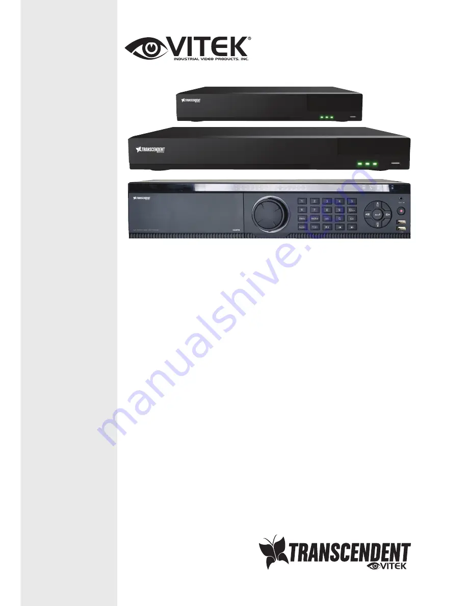
VT-TTAR Series

Transcendent Series 4, 8, 16, and 32 

Channel HD-TVI / AHD / 960H / IP 

Digital Video Recorders

Summary of Contents for Transcendent VT-TTAR Series

Page 1: ...splay Record Playback Backup Remote Access 1 Internal SATA2 SATA3 HDD Slot supporting up to 6TB VT TTAR410 VT TTAR810 2 Internal SATA2 SATA3 HDD Slots supporting up to 12TB VT TTAR1620 8 Internal SATA2 SATA3 HDD Slots supporting up to 48TB VT TTAR3280 Applications for iOS Android Remote Viewing over the Internet via Web Browser or LAN Mac OS Client CMS Central Management Software Included Supports...

Page 2: ...r Clean only with a dry cloth l Do not block any ventilation openings and ensure proper ventilation around the machine l Do not power off the device at normal recording condition l This machine is for indoor use only Do not expose the machine in rain or moist environment In case any solid or liquid get inside the machine s case please turn off the device immediately and get it checked by a qualifi...

Page 3: ...ion 17 3 Wizard Main Interface 17 3 1 Startup Wizard 17 3 2 Main Interface 21 3 2 1 Main Interface Introduction 21 3 2 2 Setup Panel 23 3 2 3 Main Functions 25 4 Camera Management 26 4 1 Signal Access Set 26 4 2 Add Edit Camera 26 4 2 1 Add Camera 26 4 2 2 Edit Camera 28 4 3 Add Edit Camera Group 28 4 3 1 Add Camera Group 28 4 3 2 Edit Camera Group 29 5 Live Preview Introduction 29 5 1 Preview Int...

Page 4: ...chedule 47 7 3 2 Record Schedule Configuration 50 7 4 Record Mode 50 7 4 1 Manual Recording 50 7 4 2 Timing Recording 51 7 4 3 Motion Based Recording 51 7 4 4 Sensor Based Recording 51 7 5 Disk Management 51 7 5 1 Storage Mode Configuration 51 7 5 2 View Disk and S M A R T Information 52 8 Playback Backup 52 8 1 Instant Playback 52 8 2 Playback Interface 53 8 3 Record Search Playback 55 8 3 1 Sear...

Page 5: ... 69 10 1 Account Management 69 10 1 1 Add User 70 10 1 2 Edit User 71 10 2 User Login Logout 72 10 3 Permission Management 72 10 3 1 Add Permission Group 72 10 3 2 Edit Permission Group 74 10 4 Black and White List 74 11 Device Management 74 11 1 Network Configuration 74 11 1 1 TCP IPv4 Configuration 74 11 1 2 Port Configuration 75 11 1 3 DDNS Configuration 76 11 1 4 E mail Configuration 78 11 1 5...

Page 6: ... 83 11 7 View System Information 83 12 Remote Surveillance 84 12 1 Web LAN Access 84 12 2 Web WAN Access 84 12 3 Web Remote Control 86 12 3 1 Remote Preview 86 12 3 2 Remote Playback 89 12 3 3 Remote Backup 90 12 3 4 Remote Configuration 90 ...

Page 7: ...cameras OSD video parameters mask motion and so on l Support a maximum of 8 user permission groups including Administrator Advanced and Ordinary which are the default permission groups of the system l Support a maximum of 16 users to be created multiple web clients login by using one username at the same time and the user s permission control to be enabled or disabled l Support a maximum of 10 web...

Page 8: ... recording l Support pre recording and delay recording configuration of the event recording Record Playback l Support time scale operation in quick playback and the playback date and time can be set randomly by scrolling the mouse the time interval of the time scale can be zoomed l Support record searching by time slice time event tag l Support time view and camera view in searching by time slice ...

Page 9: ...ce operations including remote upgrading and system restart l Support remote camera configuration of the DVR including video parameters image quality and so on l Support remote searching playback and backup of the DVR l Support manual alarm to be triggered and cleared remotely l Support NVMS or other platform management software to access the DVR and manage it l Support NAT function and QRCode sca...

Page 10: ... light is blue AUDIO 1 Adjust audio 2 Increase the value in setup P T Z 1 Enter PTZ mode 2 Decrease the value in setup MENU Enter Menu in live INFO Check the information of the device BACKUP Enter backup mode in live SEARCH Enter search mode in live Exit Exit the current interface Manually record Play Pause Speed down Speed up 1 9 Input digital number and select camera 0 Input number 0 the number ...

Page 11: ...larm 4 GND Grounding 5 VIDEO IN 4 CH video inputs 6 AUDIO OUT Audio output 7 CVBS CVBS video output connect to monitor 8 VGA Connect to monitor 9 HDMI Connect to high definition display device 10 LAN Network port 11 USB Connect USB storage device or USB mouse 12 DC12V DC12V power input 13 RS485 Connect to keyboard or speed dome A is TX B is TX No Name Descriptions ...

Page 12: ... Connect to monitor 10 LAN Network port 11 RS485 Connect to keyboard or speed dome A is TX B is TX 12 USB Connect USB storage device or USB mouse 13 DC12V DC12V power input No Name Descriptions 1 RS485 Connect to keyboard or speed dome A is TX B is TX 2 AUDIO IN Audio input 3 VIDEO IN 16 CH video inputs 4 HDMI Connect to high definition display device 5 VGA Connect to monitor 6 LAN Network port 7 ...

Page 13: ...hones amplifier etc l Alarm Connections Some models may support this function Take 16 CH alarm inputs and 1 CH alarm output for example Alarm Input Alarm IN 1 16 are 16 CH alarm input interfaces There are no type requirements for sensors NO type and NC type are both available The way to connect sensor and the device is as shown below The alarm input is an open closed relay If the input is not an o...

Page 14: ...k from the RS485 terminal block and then loosen the screws on the connecting block insert signal cables into Y and Z port separately Y is TX Z is TX and tighten the screws Next connect connecting block back into terminal block Finally connect the video cable of the speed dome to the video input interface of the DVR Type 2 Disconnect connecting block from the RS485 terminal block and then loosen th...

Page 15: ...icking OK button Disconnect the power By mouse Click StartàShutdown to pop up the Shutdown window Select Shutdown in the window The unit will power off by clicking OK button Disconnect the power 2 2 Remote Control Uses two AAA size batteries Open the battery cover of the remote control Insert batteries Please observe the polarity and Replace the battery cover Key points to check in case the remote...

Page 16: ...Z camera Preset Button To enter into preset setting in PTZ mode Cruise Button To go to cruise setting in PTZ mode Track Button Not used Wiper Button Not used Light Button Not used Clear Button Not used Fn2 Button Not used Info Button Get information about the device To control playback Play Pause Stop Previous Frame Next Frame Speed Down Speed Up Snap Button To take snapshots manually Search Butto...

Page 17: ...nd the panel will disappear automatically after you move the mouse away from it Ø Mouse control in text input Move the mouse to the text input box and then click the box The input keyboard will pop up automatically 2 4 Text input Instruction Button Function REC Record manually Search To enter search mode MEUN To enter menu Exit To exit the current interface ENTER To confirm the choice or setup Dir...

Page 18: ...mon Button Operation Button Meaning Show the menu list Change the sequence of the list Change the camera displaying mode Close the current interface Click it to go to the earliest date of camera recording Click it to go to the latest date of camera recording 3 Wizard Main Interface 3 1 Startup Wizard The disk icons will be shown on the top of the startup interface You can view the number and statu...

Page 19: ...ord next time Click Edit Security Question to set questions and answers for password security of admin If you forget the password please refer to Q4 in Appendix A FAQ for details Click Next to continue or click Cancel to exit the wizard Date and Time Configuration The date and time of the system need to be set up if you use the wizard for the first time Refer to the following figure Set the time z...

Page 20: ...led or manually input them Input the HTTP port RTSP port and Server port please see 11 1 2 Port Configuration for details Click Next to continue QRCode You can scan the QRCode using the mobile client which is installed on the mobile phone or PAD to log in the mobile client instantly Please refer to 12 1 Mobile Client Surveillance for details Add Camera Click Refresh to refresh the list of online I...

Page 21: ...amera Click OK to save the settings Click to edit the added camera as shown on the above right Input the new camera name IP address port username and the password of the camera You can click Test to test the effectiveness of the inputted information Click OK to save the settings You can change the camera name only if it s an analog camera or the added IPC is online Click Next to continue Disk Sett...

Page 22: ...n the interface as shown below and then click OK button to save the settings See 7 1 1 Mode Configuration for details Manual Set the Sensor Record Motion Record and Schedule Record of each camera Click OK to save the settings See 7 1 1 Mode Configuration for details 3 2 Main Interface 3 2 1 Main Interface Introduction ...

Page 23: ...layback interface for playback operations 8 2 Playback Interface Introduction click to go to the playback interface For instance if you choose 5 minutes ago as the default playback time you can playback the recording from the past five minutes Manual record button Click it to enable disable record Manual alarm button Click it to trigger or clear the alarm out manually in the popup window Record st...

Page 24: ...witch to the display mode for previewing Introduction of area Icon Button Meaning Shows the current login user Click to go to record search interface see 8 3 Record Search Playback for details Click to go to playback interface click on the tool bar at the bottom of the live preview interface to set the default playback time see 8 2 Playback Interface Introduction for details Click to go to the bac...

Page 25: ...amera module provides convenient links such as Add Camera Edit Camera Image Settings Motion and PTZ Click Camera to go to the camera management interface as shown below There are some function items on the left side of the camera management interface Click each item to go to corresponding interface or window For instance click Add Camera to pop up the window as shown below to add IP Camera ...

Page 26: ...f Encode Parameters and Record Schedule and so on Please see Chapter 7 Record Disk Management for details Ø Disk The module covers the functions of Disk Management Storage Mode and Disk Information and so on Please see Chapter 7 Record Disk Management for details Ø Alarm The module covers the functions of Sensor and Motion Alarm Handling and Alarm Out Settings Please see Chapter 9 Alarm Management...

Page 27: ... check TVI in the following interface to show the camera image if you check AHD then there will be no image or the image has no color The default selection of the signal is Auto If you check Auto then the image of the camera will be shown regardless of the access signal type LITE if you check LITE the resolution will change from 1920 x 1080 to 960 x 1080 This will allow you to record at 30fps 4 2 ...

Page 28: ...s IP address username and password and so on Click Default Password to set the default username and password of each camera Ø Add Manually Input the IP address port username and password of the camera and then select the protocol Click Test to test the effectiveness of the inputted information and then click Add button ...

Page 29: ...terface as shown below Click to view the live image of the camera in the popup window Click to edit the camera see Add camera in 3 1Startup Wizard for details Click to delete the IP camera 4 3 Add Edit Camera Group 4 3 1 Add Camera Group Click Edit Camera Group in the above interface to go to the interface as shown below Click to pop up the window as shown below Set the group name and dwell time i...

Page 30: ...eview Introduction 5 1 Preview Interface Introduction The connected analog camera will be added automatically in the live preview interface for previewing You need to add IP camera manually for previewing see 4 2 1 Add Camera for details Refer to the interface as shown below drag one camera in the preview window to another window for camera window exchanging ...

Page 31: ...nable audio You can listen to the camera audio by enabling audio Snap Click to pop up the snapshot window Click Save in the window to save the image Click Export to export the image PTZ Control Click to go to PTZ control interface See Chapter 6 PTZ for details Zoom In Click to go to single channel zoom interface Click it to go to image adjustment interface Refer to 5 3 4 Image Adjustment for detai...

Page 32: ...splay modes classified by surveillance areas priorities and so on Refer to the picture below Double click one display mode in the display mode list to view the live images in this mode Ø Add Display Mode Method One Click Customize Display Modes in the above interface and then set the screen mode Add the cameras and adjust the cameras display sequence as required ...

Page 33: ...e Click Customize Display Modes tab in the live preview interface and then select one display mode in the list Click Rename to edit the display mode name click Delete to delete the display mode 5 2 2 Quick Sequence View You can start quick sequence view if the scheme has not been created If the scheme has been created please refer to 5 2 3 Scheme View in Sequence for details Go to the live preview...

Page 34: ...a scheme in area and then click the screen mode button on the tool bar to set the screen mode of the scheme b Select a camera window in area and then double click the camera or group in area The camera or group will be added into the selected window One camera in the same scheme cannot repeat You can right click and select Clear in area to remove a single camera or click to remove all the cameras ...

Page 35: ... of all the schemes select the dwell time and click Apply to start playing the schemes in sequence in output 2 5 3 Preview Image Configuration 5 3 1 OSD Settings Click StartàSettingsàCameraàImageàOSD Settings to go to the interface as shown below Select the camera input the camera name or double click the camera name in the camera list to change the camera name enable or disable the name and time ...

Page 36: ...ore the image settings to the factory default settings 5 3 3 Mask Settings Some areas of the image can be masked for privacy Up to four mask areas can be set for each camera Click StartàSettingsàCameraàImageàMask Settings to go to the interface as shown below Select the camera and enable the mask Click Draw button and then drag the mouse on the image area to set the mask area click Delete button t...

Page 37: ...tment interface Ø Image Adjustment Select the camera and then click Image Adjustment to go to image adjustment tab Refer to the above picture Drag the slider to set the camera s brightness contrast saturation and hue value Check sharpen wide dynamic and denoise and then drag the slider to set the value Click Default button to set these parameters to default values ...

Page 38: ...evel of the whole image and provide clearer images with details Denoise Adopt the noise reduction technology to decrease the noise and make the image more thorough Increasing the value will make the noise reduction effect better but it will reduce the image resolution White Balance White balance is the white rendition function of the camera to adjust the color temperature according to the environm...

Page 39: ...ally when the camera is switching day night mode Time Interval It is the time interval when camera lens is auto focusing The interval can be set in the drop down list 6 PTZ 6 1 PTZ Control Interface You can control the dome or PTZ Click on the tool bar at the bottom of the live preview window to go to the PTZ control interface as shown below You can select another dome or PTZ on the top right of t...

Page 40: ...interface Ø Analog Joystick Control The analog joystick on the left side of the interface provides quick PTZ control The dome or PTZ will rotate when you drag the analog joystick The farther you drag the analog joystick from the middle of the image the faster the dome or PTZ rotates The dome or PTZ will stop rotating when you stop dragging the analog joystick Ø 3D Control Click the camera image on...

Page 41: ...old the right button to zoom out the image Move the cursor of the mouse to the camera image and then slide the scroll wheel of the mouse forward to zoom in the image slide the scroll wheel of the mouse backward to zoom out the image Ø OSD Setting Go to PTZ protocol setting interface and then set the protocol to COC before you call the OSD Click OSD to go to camera OSD setting interface Click to st...

Page 42: ...t list and then save the preset position after adjusting the dome s direction click in the preset list to call the preset click Delete button to delete the selected preset You can also go to preset setting interface for preset setting see 6 2 Preset Setting for details Ø Cruise Setting Click Cruise to go to cruise operation tab and then click Add button to pop up a window as shown below left You c...

Page 43: ... the interface as shown below Ø Add preset Select camera and then click Add button to add preset or click in the camera list on the right side of the interface to display the preset information of the dome and then click to add preset The operations of the Add Preset window are similar to that of the PTZ control interface please see 6 1 PTZ Control Interface Introduction for details Ø Edit preset ...

Page 44: ...put the a cruise name and then click to save the cruise name Click Add Preset to add preset to the cruise Click to delete the preset from the cruise Click one preset in the preset list and then click to move down the preset and click to move up the preset Click to start the cruise and click to stop it Ø Delete Cruise Click in the camera list on the right side of the interface to display the cruise...

Page 45: ... Address The address of the PTZ device Baud Rate Baud rate of the PTZ device Range from 110 300 600 1200 2400 4800 9600 19200 34800 57600 115200 230400 460800 921600 7 Record Disk Management 7 1 Record Configuration 7 1 1 Mode Configuration Please format the HDDs before recording refer to 7 5 Disk Management for details Click StartàSettingsàRecordàMode Settings to go to the mode settings interface...

Page 46: ... all the time sensor alarm record will be started when sensor alarm happens Always 24ⅹ7 Record Motion Record Sensor Record Normal record is enabled all the time motion sensor alarm record will be enabled when motion sensor alarm happens Select one auto mode to pop up the corresponding window Set the video encode resolution FPS bitrate and audio of each camera and then click OK to save the settings...

Page 47: ... alarm record time and expiration time of each camera and then click Apply to save the settings Pre alarm Record Time set the time to record before the actual recording begins Post alarm Record Time set the time to record after the actual recording is finished Expiration Time set the expiration time for recorded video If the set date is overdue the recorded data will be deleted automatically 7 2 E...

Page 48: ...ick StartàSettingsàRecordàRecord ScheduleàEdit Schedules to go to the interface as shown below 24ⅹ7 24ⅹ5 and 24ⅹ2 are the default schedules you cannot edit or delete 24ⅹ7 while 24ⅹ5 and 24ⅹ2 can be edited and deleted Click the schedule name to display the detailed schedule information on the left side of the interface The seven rows stand for the seven days in a week and each row stands for 24 hou...

Page 49: ...Transcendent DVR Series 48 Click to add a new schedule Refer to the picture below Set the schedule name and schedule time and then click Add to save the schedule You can ...

Page 50: ...he start and end time in the window and then click OK to save the settings Click All to set all day recording click Reverse to swap the selected and unselected time in a day click Clear All to clear all the selected area in a day Click Copy To to copy the schedule of the day to other days Refer to the picture below Check the days in the window and then click OK to save the settings Ø Set Week Sche...

Page 51: ...pply to save the settings Go to Edit Schedules interface and then click to edit the schedule The settings of Edit Schedule are similar to that of the Add Schedule Click to delete the schedule 7 4 Record Mode 7 4 1 Manual Recording Method One Click on the tool bar at the bottom of the live preview interface to enable recording of the camera Method Two Go to live preview interface and then right cli...

Page 52: ...d Recording Set the sensor based recording schedule of each camera See 7 3 Schedule Setting for details Set the NO NC type of sensor enable the sensor alarm and then check and configure the Record See 9 1 Sensor Alarm for details 7 5 Disk Management Click StartàSettingsàDiskàDisk Management to go to disk management interface You can view the DVR s disk number and disk status and so on in the inter...

Page 53: ...sk and camera can only be added into one group Select a disk group and then click in the disk or camera row to pop up a window Check the disks or cameras in the window and then click Add 7 5 2 View Disk and S M A R T Information Click StartàSettingsàDiskàView Disk Information to view the HDD information click S M A R T Information to view the working status of the HDD Refer to the picture below 8 ...

Page 54: ...k interface as shown below click on the tool bar at the bottom of the live preview interface to set the default playback time The cameras will playback their recordings in the playback interface automatically You can also add the playback camera manually The buttons on the tool bar area at the bottom of the playback interface are introduced in the table below Button Meaning Start button Click to p...

Page 55: ...n and the tag information Backup button Drag the mouse on the time scale to select the time periods and cameras and then click the button to back up the record Backup status button Click to view backup status Back button Click to return to live view Introduction of area Button Meaning Click to go to record search interface see 8 3 Record Search Playback for details Click to go to backup interface ...

Page 56: ...e the scroll wheel of the mouse on the time scale to show the hidden time on the top or bottom of the timeline You can also click to show the hidden time on the top of the timeline or click to show the hidden time on the bottom of the timeline Drag the slider bar at the bottom of the time scale to show the hidden cameras The recording time scale shows different record types with different colors T...

Page 57: ...t recorded data exist Refer to the picture below Drag the color blocks on the time scale to select the recorded data and then click Backup button to pop up a window select the device backup path and backup format in the window and then click Backup button to start the backup Click Playback button to play the recording in the playback interface refer to 8 2 Playback Interface Introduction for detai...

Page 58: ... go back to the upper interface 8 3 2 Search Playback by Time Click StartàSearchàBy Time to go to By Time tab as shown below Click on the bottom of the interface to add playback camera Click Modify on the top right corner of the camera window to change the camera and click Clear to remove the camera Click the camera window to play the recording in the small playback box on the left side of the int...

Page 59: ...the event type in the interface as required Click to set the start time and end time on the top left of the interface Check cameras on the left side of the interface and then click to search the recording The found recordings will be displayed in the list Click in the list to play back the recording in the popup window Select one ...

Page 60: ...b Click in the interface to play the recording Click to edit the tag name Click to delete the tag 8 4 Backup The recorded data and the snapped pictures can be backed up through network or USB U disk or USB mobile HDD The file system of the backup devices should be FAT32 format 8 4 1 Backup by Time Click StartàBackupàBy Time to go to the By Time tab Click in the picture section to pop up the add ca...

Page 61: ...ackup format and path and then click Backup button to start the backup 8 4 2 Backup by Event Click StartàBackupàBy Event to go to By Event tab Note If you back up the recording in private format the system will back up a RPAS player to USB device automatically The private format recording can be played by RPAS player only ...

Page 62: ...ove in the list and then click Backup button to back up the record data 8 4 3 Image Management Click StartàBackupàImage Management to go to Image Management tab The system will display all the snapped images automatically in the list Click to delete the image Click to pop up the Export window Select the device name and save path in the window and then click Save button Click to pop up the View Ima...

Page 63: ... handling of each camera Click StartàSettingsàAlarmàSensor Alarm to go to the following interface Select the alarm type NO or NC according to trigger type of the sensor Enable the sensor alarm of each camera Check the Record Snap Alarm out and Preset and enable or disable the Buzzer Pop up Video Pop up Message Box and E mail as required Click Apply to save the settings The configuration steps of t...

Page 64: ... To add presets please see 6 2 Preset Setting for details Buzzer if enabled the system will begin to buzz when the sensor alarm is triggered To set the delay time of the buzzer please see 9 4 4 Buzzer for details Pop up Video After camera setting the system will pop up the corresponding video automatically when the sensor alarm is triggered To set the duration time of the video please see 9 4 3 Di...

Page 65: ...d would not detect any other motion specific to camera for 10 seconds If there is another motion detected during this period it will be considered as continuous movement otherwise it will be considered as a single motion Drag the camera image to set the motion area You can set more than one motion area Click All to set the whole camera image as the motion area Click Reverse to swap the motion area...

Page 66: ...guration interface 9 3 Exception Alarm 9 3 1 IPC Offline Settings Click StartàSettingsàAlarmàExceptionàIPC Offline Settings to go to the interface as shown below Enable or disable Snap Alarm out Preset Buzzer Pop up Video Pop up Message Box and E mail The IPC Offline Settings are similar to that of the sensor alarm see 9 1 Sensor Alarm for details Click Apply to save the settings 9 3 2 Video Loss ...

Page 67: ...xception Handling Settings Click StartàSettingsàAlarmàExceptionàException Handling Settings to go to the interface as shown below Enable or disable Alarm out Buzzer Pop up Message Box and E mail The exception handling settings are similar to that of the sensor alarm see 9 1 Sensor Alarm for details Click Apply to save the settings 9 4 Alarm Event Notification 9 4 1 Alarm out Click StartàSettingsàA...

Page 68: ...ration interface Set the e mail address of the recipients See 11 1 4 E mail Configuration for details 9 4 3 Display Click StartàSettingsàAlarmàEvent NotificationàDisplay to go to the display configuration interface Set the duration time of the pop up video and the pop up message box Click Apply to save the settings 9 4 4 Buzzer Click StartàSettingsàAlarmàEvent NotificationàBuzzer to go to the buzz...

Page 69: ...Click Trigger to start alarm Click Clear to stop alarm 9 6 View Alarm Status Click StartàSettingsàAlarmàAlarm Status or click on the tool bar at the bottom of the live preview interface to view the alarm status Click Clear button to stop the buzzer when the buzzer alarm happens Click to view the detail information as shown below ...

Page 70: ...e box and then click to jump to the specified page Click to view the exception alarm information in the previous next page Click to play the alarm record 10 Account Permission Management 10 1 Account Management Click StartàSettingsàAccount and AuthorityàAccountàEdit User to go to the interface as shown below ...

Page 71: ...u can manually add new permission group see 10 3 1 Add Permission Group for details The user admin owns all the permissions and it can manage the system s accounts Group Administrator owns all the permissions displayed in area and its permissions cannot be changed while the permissions of Advanced and Ordinary can be changed 10 1 1 Add User Click StartàSettingsàAccount and AuthorityàAccountàAdd Us...

Page 72: ... you forget the password please refer to Q4 in Appendix A FAQ for details Ø Modify Password Only the password of admin can be modified Click Modify Password to pop up a window Input the current password and then set new password Click OK to save the settings Ø Recover Password Click Recover Password to reset the password to 123456 Ø Edit User Click Edit User to pop up the window as shown below The...

Page 73: ...opup window Click Login button to log in the system Logout Click StartàLogout or click StartàShutdown to pop up the Shutdown window Select Logout in the window and then click OK button to log out the system 10 3 Permission Management 10 3 1 Add Permission Group Click StartàSettingsàAccount and AuthorityàAccountàEdit Permission Group to go to the interface as shown below ...

Page 74: ...Transcendent DVR Series 73 Click to add permission group Set the group name check the permissions as required and then set the Local and Remote permissions Click Add to save the settings ...

Page 75: ...List the PC client of which the IP address is in the allow list can access DVR remotely while the PC client in the block list cannot Add IP segment MAC Click Add IP or Add MAC button and then check Enable in the popup window only if you check it can the IP segment MAC you add be effective Enter the IP segment MAC and then click OK button In the above interface click to edit IP segment MAC click to...

Page 76: ...ave the settings 11 1 2 Port Configuration Click StartàSettingsàNetworkàPort to go to the interface as shown below Input the HTTP port server port and RTSP port of the DVR and then click Apply to save the ports HTTP Port the default HTTP port of the DVR is 80 The port number can be changed to others like 81 The port is used for internet remote access If you want to access the DVR ...

Page 77: ...ough domain name You can access the DVR easily if the DDNS is enabled and configured Click StartàSettingsàNetworkàDDNS to go to the interface as shown below Check Enable and then select the DDNS type Input the server address domain name username and password according to the selected DDNS type Click Test to test the effectiveness of the inputted information Click Apply to save the settings You wil...

Page 78: ...77 Click Registration button to go to the interface as shown below Set the DDNS account information username password and so on and then click Submit button to save the account Create domain name and then click Request Domain ...

Page 79: ...ivpddns com 81 in the IE address bar and then press Enter key to go to the IE client 11 1 4 E mail Configuration Click StartàSettingsàNetworkàE mail to go to the following interface Input the sender s e mail address name password SMTP server and SMTP port you can click Default to reset the SMTP port to the default value and then enable or disable the SSL and attaching image Click Test to pop up a ...

Page 80: ...delete the recipient in the list Click Apply to save the settings Click Edit Sender to go to the e mail configuration interface of the sender 11 1 5 UPnP Configuration By UPnP you can access the DVR through IE client which is in WAN via router without port mapping Click StartàSettingsàNetworkàUPnP to go to the following interface Make sure the router supports UPnP function and the UPnP is enabled ...

Page 81: ...ess the DVR such as http 183 17 254 19 81 11 1 6 NAT Configuration Click StartàSettingsàNetworkàNAT to go to the interface for NAT configuration Check Enable and then select the NAT server address nat autonat com by default Click Apply to save the settings 11 1 7 View Network Status Click StartàSettingsàNetworkàNetwork Status to view the network status or click on the tool bar at the bottom of the...

Page 82: ... Date and Time Configuration Click StartàSettingsàSystemàBasicàDate and Time to go to the interface as shown below Set the system time date format time format and time zone of the DVR The default time zone is GMT 08 If the selected time zone includes DST the DST of the time zone will be checked by default Click Apply to save the settings You can manually set the system time or synchronize system t...

Page 83: ...ace Select the USB device in Device Name option and go to the path where the upgrade software exists Select the upgrade software and then click Upgrade The system may automatically restart during upgrading Please wait for and do not power off the DVR during upgrading 11 5 Backup and Restore You can back up the configuration file of the DVR by exporting the file to another storage device you can re...

Page 84: ... go to the log view interface Select the log main type click to set start time and end time and then click Search button The found log files will be displayed in the list Choose the log file in the list and then click Export button to export the log file Click on the Content title bar to pop up a menu list Check contents in the menu list and then the log list will show the checked log contents onl...

Page 85: ...ls Enable NAT and then set the NAT server address Please refer to 11 1 6 NAT Configuration for details Open IE browser on a computer input the NAT server address www autonat com in the IE address bar and then press enter to go to the interface as shown below download and install the relative plugin according to the popup tip if you access the DVR through NAT for the first time Notes 1 Please make ...

Page 86: ...face Input the username and password of the DVR in the interface and then click Login to go to the live preview interface Ø Router Access Click StartàSettingsàNetworkàTCP IPv4 to go to the TCP IPv4 interface Set the IP address subnet mask gateway preferred DNS and alternate DNS of the DVR Set the HTTP port it is suggested to modify the HTTP port because the default HTTP port 80 might be taken and ...

Page 87: ... the password of the current login user Input current password and then set a new password in the popup window Click OK button to save the new password Local Settings click it to change the local settings Set the snapshot number and click Browse to set the snapshot path and record path as shown below Click Apply button to save the settings 12 3 1 Remote Preview Click Live Display in the remote int...

Page 88: ... view the cameras You can view the number of all the added cameras and the online cameras For instance the left number 3 in on the left panel stands for the number of online cameras the right number 4 stands for the number of all the added cameras Input the camera name in the search box and then click to search the camera Click to refresh the camera list l View Group Click to view the groups The t...

Page 89: ...k to start recording Click to stop recording Click to enable talk with the DVR Ø Right Panel Introduction Click on the right panel to show the panel and click to hide the panel Click at the bottom of the panel to go to PTZ panel Click to go to Operation panel Click one camera window in the preview area and then click to set the camera s live preview stream and record stream to main stream in manua...

Page 90: ... click to stop rotating the dome Drag the slider to adjust the rotating speed of dome Click to zoom in out camera image Click to increase decrease the focal length Click to increase decrease the iris of the dome Click to view the preset list and then click the button in the list to call the preset Click to view the cruise list and then click the corresponding buttons in the list to start or stop t...

Page 91: ...up in the remote interface to go to the backup interface You can back up the recording by event or by time Ø By Event Check the recording type on the left side of the interface and then click to set the start time and end time check the cameras and then click on the right side to search the recording the found record data will be displayed in the list check the recorded data in the list and then c...

Page 92: ...Transcendent DVR Series 91 ...

Page 93: ...Transcendent DVR Series 92 ...

Page 94: ...Transcendent DVR Series 93 ...

Page 95: ...Transcendent DVR Series 94 ...

Page 96: ...2fps per channel 1920 x 1080 4 CH Embedded Linux 1 x HDMI 1080p 1 x VGA 1080p 1 x BNC Spot Analog Pentaplex Live Display Record Playback Backup Remote Access Input RCA x 4 Output RCA x 1 Yes 768Kbps 8Mbps VBR CBR 6 level Manual Timer Motion Sensor Lock Unlock Reserve time Redundancy Time Motion Sensor Single or Multi channel Play Pause FF FB Shutter Control Jog Digital zoom 4 Alarm inputs 1 Alarm ...

Page 97: ...s 12fps per channel 1920 x 1080 8 CH Embedded Linux 1 x HDMI 1080p 1 x VGA 1080p 1 x BNC Spot Analog Pentaplex Live Display Record Playback Backup Remote Access Input RCA x 4 Output RCA x 1 Yes 768Kbps 8Mbps VBR CBR 6 level Manual Timer Motion Sensor Lock Unlock Reserve time Redundancy Time Motion Sensor Single or Multi channel Play Pause FF FB Shutter Control Jog Digital zoom 4 Alarm inputs 1 Ala...

Page 98: ...00fps 12fps per channel 1920 x 1080 16 CH Embedded Linux 1 x HDMI 1080p 1 x VGA 1080p 1 x BNC Spot Analog Pentaplex Live Display Record Playback Backup Remote Access Input RCA x 4 Output RCA x 1 Yes 768Kbps 8Mbps VBR CBR 6 level Manual Timer Motion Sensor Lock Unlock Reserve time Redundancy Time Motion Sensor Single or Multi channel Play Pause FF FB Shutter Control Jog Digital zoom 4 Alarm inputs ...

Page 99: ...fps 15fps per channel 1920 x 1080 16 CH Embedded Linux 1 x HDMI 1080p 1 x VGA 1080p 1 x BNC Spot Analog Pentaplex Live Display Record Playback Backup Remote Access Input RCA x 16 Output RCA x 1 Yes 768Kbps 8Mbps VBR CBR 6 level Manual Timer Motion Sensor Lock Unlock Reserve time Redundancy Time Motion Sensor Single or Multi channel Play Pause FF FB Shutter Control Jog Digital zoom 16 Alarm inputs ...

Page 100: ... shipping and or delivery charges will be the responsibility of the customer If upon return inspection a product is determined to be in good working order or shows evidence of misuse the customer will be responsible for full payment of the original product purchased as well as the replacement product Beyond the first 6 month period for the remainder of the warranty VITEK S responsibility shall be ...

Reviews: