VITEK
FEATURES:
• 4, 8, 16, 32, and 64 Channel Stand-alone Real-time IP Network Video Recorders
• Full 8 Megapixel Real-time recording & playback
• 4K HDMI & VGA Video Outputs
• H.265 / H.264 Video Compression
• Plug and Play & Auto configuration for many leading ONVIF compliant IP Camera models
• Internal PoE Switch (VT-TNR414P, VT-TNR818P, VT-TNR1616P, and VT-TNR3216P)
• 1 Gigabit LAN / Dual 1 Gigabit LAN (VT-TNR6480)
• Pentaplex: Live Display / Record / Playback / Backup / Remote Access
• Supports SATA2/SATA3 HDD
• Applications for iOS® & Android®
• Remote Viewing over the Internet via Web Browser or LAN
• Mac OS® Client & CMS Central Management Software Included
• Supports both Dynamic and Static IP Addresses
• Web-based remote configuration
• Control locally via Front Panel Controls, USB Mouse, or with the Included IR Remote
control
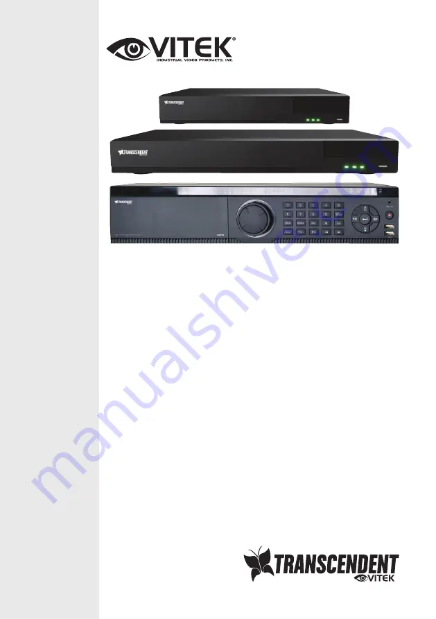
VT-TNR Series
Transcendent Series 4, 8, 16, 32, and
64 Channel 8 MegaPixel H.265 Real
Time Network Video Recorders with
4K HDMI Output