Visiosat NAUTIC 55cm, Installation And User Manual
The Visiosat NAUTIC 55cm is a high-quality satellite dish designed for exceptional performance. To assist users in the installation and setup process, we offer a comprehensive Installation and User Manual. This manual can be easily accessed and downloaded for free from our website, ensuring a seamless experience for our customers.
Share
Download


Reviews:
No comments
Related manuals for NAUTIC 55cm
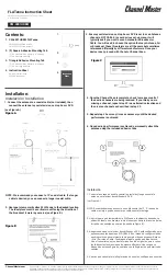
FLATenna
Brand: Channel Master Pages: 2

THOMSON ANT537
Brand: Hama Pages: 16

EXTERMINATOR II
Brand: PCS Electronics Pages: 13

WMM2G-6-60
Brand: Panorama Antennas Pages: 8

BAS-1131 DIAPAZON-UHF
Brand: BAS Pages: 2

ANTDVBT6
Brand: Velleman Pages: 12

436CP16
Brand: M2 Antenna Systems Pages: 6

EM-9041
Brand: Emos Pages: 28

Falcon KF1000
Brand: KING Pages: 36

9711QOR-86
Brand: Sea Tel Pages: 243

Omni AMO-5G13
Brand: air MAX Pages: 16

TRINOVA BOSS
Brand: Televes Pages: 12

Emerge HGA51G-DIR30
Brand: Avocent Pages: 2

VH226F
Brand: RCA Pages: 6

DIRECTV
Brand: RCA Pages: 48

Zenith06
Brand: GeoMax Pages: 104

NAA-301
Brand: Naxa Pages: 2

HDA-1000
Brand: Monoprice Pages: 2


