background image

Unitronics  

Vision™ OPLC™ 

Installation Guide 
V290 (Color) 

This guide provides basic information for Unitronics’ LCD color touchscreen models  
V290-19-C30B and V290-19-T40B.   

General Description 

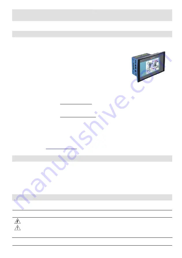
Vision OPLCs are programmable logic controllers that comprise an integral operating panel. 
Operating panel features differ according to model.  

The V290-19-C30B and V290-19-T40B offer a color touchscreen, 
which displays a virtual keyboard when the application requires the 
operator to enter data. 

Communications 


2 isolated RS232/RS485 ports 
and a CANbus port.  
The user can order and install an 
additional port. Available port 
types are: RS232/RS485, and 
Ethernet. 

V290 (Color Screens) 
Touchscreen only 

I/O Options 

Vision supports up to 171 digital, high-speed, and analog I/Os via modules. 
Number of I/Os and types vary according to module. 

Snap-in I/O Modules
Plug into the back of the controller to provide an on-board I/O 
configuration. 
I/O Expansion Modules
Via adapter, use up to 8 I/O Expansion Modules comprising up to 
128 additional I/Os.  

Programming 

Write both the HMI and Ladder control application using VisiLogic freeware. 

The Vision User Guide and the product’s technical specification sheet contain additional information. 
These documents are located on the Unitronics’ Setup CD. They may also be downloaded from the 
Technical Library at 

www.unitronics.com

.

Standard Kit Contents 

Vision controller 

Programming cable + RS232 adapter 

Mounting brackets (x4) 

Grounding hardware 

3 pin power supply connector 

Rubber seal 

5-pin CANbus connector 

Unitronics’ Setup CD 

CANbus network termination resistor 


Danger Symbols 

When any of the following symbols appear, read the associated information carefully. 

Symbol Meaning  Description 

Danger 

The identified danger causes physical and property damage. 

Warning 

The identified danger could cause physical and property damage. 

Caution

 Caution  Use 

caution. 

Summary of Contents for OPLC V290

Page 1: ...ules Plug into the back of the controller to provide an on board I O configuration I O Expansion Modules Via adapter use up to 8 I O Expansion Modules comprising up to 128 additional I Os Programming Write both the HMI and Ladder control application using VisiLogic freeware The Vision User Guide and the product s technical specification sheet contain additional information These documents are loca...

Page 2: ...r property damage Do not attempt to use this device with parameters that exceed permissible levels To avoid damaging the system do not connect disconnect the device when power is on Environmental Considerations Do not install in areas with excessive or conductive dust corrosive or flammable gas moisture or rain excessive heat regular impact shocks or excessive vibration in accordance with the stan...

Page 3: ...Dimensions 2 If you mount the controller on a metal panel earth the power supply a Bore a hole to suit the NC6 32 screw supplied with the kit b Scrape panel paint away from the contact area to ensure a conductive connection c Drive the screw into the hole d Place the following hardware screw s shank in the order shown in the accompanying figure washer ring cable shoe second washer spring and nut N...

Page 4: ... and I O Expansion Modules Installation instructions and other data may be found in the module s technical specification sheet Wiring General Do not touch live wires Unused pins should not be connected Ignoring this directive may damage the device Caution To avoid damaging the wire do not exceed a maximum torque of 0 5 N m 5 kgf cm Do not use tin solder or any substance on stripped wire that might...

Page 5: ...ections Caution Signals are related to the controller s 0V the same 0V is used by the power supply Always use the appropriate port adapters Serial Communications The serial ports are type RJ 11 and may be set to either RS232 or RS485 via DIP switches in accordance with to the table shown on page 7 Use RS232 to download programs from a PC and to communicate with serial devices and applications such...

Page 6: ...tons on the sides of the controller two on either side 2 Press the buttons and hold them down to open the locking mechanism 3 Gently rock the module from side to side easing the module from the controller Opening and Closing the Controller 1 Locate the slots on the sides of the controller 2 Open the controller by inserting a flat bladed screwdriver into the slots located on the side of the control...

Page 7: ...even pressure on all 4 corners until you hear a distinct click The module is now installed Check that all sides and corners are correctly aligned RS232 RS485 DIP Switch Settings Switch Settings 1 2 3 4 5 6 RS232 ON ON ON OFF ON OFF RS485 OFF OFF OFF ON OFF ON RS485 with termination ON ON OFF ON OFF ON Default factory setting Causes the unit to function as an end unit in an RS485 network ...

Page 8: ... all applicable laws at any time at its sole discretion and without notice to discontinue or change the features designs materials and other specifications of its products and to either permanently or temporarily withdraw any of the forgoing from the market All information in this document is provided as is without warranty of any kind either expressed or implied including but not limited to any i...

Reviews: