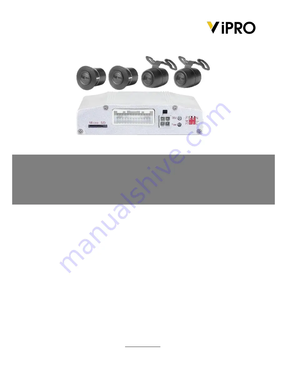
background image


AVM100 

Around View Monitoring System 

User’s Manual v1.2 

This manual was complete and correct at the time of printing. The ongoing development of the products 

may mean that the content of the user guide can change without notice. 

The manual will be kept updating periodically, and software referred as well. 


ViPRO SECURITY 

www.vipro.com.tw   


Summary of Contents for AVM100

Page 1: ...l was complete and correct at the time of printing The ongoing development of the products may mean that the content of the user guide can change without notice The manual will be kept updating periodically and software referred as well ViPRO SECURITY www vipro com tw ...

Page 2: ...uct Specifications 6 6 Installation and Debug Instructions 7 6 1 Installation Instructions 7 6 1 1 Wiring diagram 7 6 1 2 Determination of the host position 7 6 1 3 Camera wiring model 8 6 2 Debug Instructions 9 6 2 1 Debugging preparation 9 6 2 2 Debugging tool arrangement 10 6 2 3 Spreading 11 6 2 4 Debugging 12 6 25 Camera parameters Setup 15 User Manual AVM100 l v1 2 l 2014 03 ViPRO by Mobile ...

Page 3: ...in order to avoid short circuit raised by electric shock and fire 5 Please apply the system under operating voltage 6 The output voltage of the host is 3 3V only serve for the camera Please don t load any undesignated or allowed equipments 2 Product description AVM collects images around automobiles after series of intelligent algorithm processing the panorama overhead view of a vehicle is shown o...

Page 4: ... micro SD 2 Base Wire interface 3 Power Line Interface 4 power light keep on when control box is working 5 LED Light for work state blink when control box is working 6 Dail switch User Manual AVM100 l v1 2 l 2014 03 ViPRO by Mobile Cloud Corporation ...

Page 5: ...ed in debug function Not used Exit menu or return to previous menu Enter debug menu Switch display channel of the single camera display area Enter User menu or confirm the setting of user menu Switch between menu items Change menu item value User Manual AVM100 l v1 2 l 2014 03 ViPRO by Mobile Cloud Corporation ...

Page 6: ...lowing situations 1 Camera is exposure to the sun directly 2 Rainstorm or rainy days 3 Camera interface freezes or spots with clay dust or snowflakes 4 Under a weak light of the environment 5 System function 5 1 General Function 1 When the car starts the system will stay in the standby mode and it will open automatically if you put the car in reverse gear or press power button of remote control 2 ...

Page 7: ... Standby When the gear is not set in reverse mode with no operations the hosts will enter the standby mode after waiting for some times you can set up waiting time 7 View field default visual range of the system is 2 meters front 4 meters back 2 5 meters left 2 5 meters right users can increase or decrease the range base on these figures When you choose smaller the visual range will decrease 10 co...

Page 8: ...uct Specifications working voltager DC 7 36V working current 400mA DC 7 36V average power 4 8W working temperature 20 C 70 C storage temperature 30 C 85 C working humidity 10 95 video input format PAL NTSC Image processing unit video output format PAL NTSC working current 55mA DC 3 3V average power 0 6W working temperature 20 C 70 C working humidity 10 95 Camera video output format PAL NTSC User M...

Page 9: ...vice BM Connector connect all to camera Red connect to power wire of the vehicle Pink connect to ACC wire of the vehicle Black connect to the ground wire of the vehicle Brown connect to the reverse wire of the vehicle 6 1 2 Determination of the host position First confirm where to place the control box Please keep away from the place where water inflows or splashes and where is high temperature an...

Page 10: ...gnal wire of the vehicle or on any place which does not affecting vehicle s normal use figure4 3 wire should then go into the cockpit figure4 4 and finally connect to the host Fig6 4 Back camera wiring mode 3 Right left camera wiring Aware not to affect the functionality of the door glass and make sure that the camera wire would not be cut by the up and down going of the glass First run the wire f...

Page 11: ...eave enough space around it generally about 2m space meanwhile debugging suit of sharpvision is needed which contains 1 tape measure 2 professional debugging cloth fig 6 8 3 remote control Fig 6 8 specifications of debugging cloth User Manual AVM100 l v1 2 l 2014 03 ViPRO by Mobile Cloud Corporation ...

Page 12: ...k bumper is 10cm and 5cm for right and left sides Please make concrete decision for specific vehicle Rendering of laser arrangement can be found in figure 6 9 Fig 6 9 Laser rectangle schematic Measure the distance between A B C and D to determine whether laser is aligned In general if laser is chose to measure the rectangle the distance of AB or AC should be near to the one of CD or BD with allowe...

Page 13: ... of cloth coincides with point A Back the long edge of cloth aligns with CD and top right corner of cloth coincides with point D Left the long edge of cloth aligns with AC and the lower right quarter of cloth coincides with point E Right the long edge of cloth aligns with BD and top left corner of cloth coincides with point D E is a point on AC and the distance from E to A is 1 5m that is AE 1 5 F...

Page 14: ...erating the remote control so that the signal can be received quickly At first ensure that whether the cloth of front side and rear side can be totally seen by a single view of the right display screen Spreading renderings are shown as following figure 6 12 and figure 6 13 Once finished please start to debug Fig6 12 Front spreading effect Fig6 13 Rear spreading effect User Manual AVM100 l v1 2 l 2...

Page 15: ...enter the engineering mode as figure 6 14 Fig6 14 engineering mode Step 2 press the arrow keys to select panoramic stitching and OK to enter Figure 6 15 Fig6 15 Panoramic stitching menu User Manual AVM100 l v1 2 l 2014 03 ViPRO by Mobile Cloud Corporation ...

Page 16: ...ult widthes of left and right grids are 150cm Then select stitching and press OK to confirm Processing will be displayed on the screen and the system can complete the splice within 30 seconds Finally the user interface will exit from engineering mode and displays the real picture as shown below Fig6 16 Front spreading effect Fig6 17 Rear spreading effect User Manual AVM100 l v1 2 l 2014 03 ViPRO b...

Page 17: ...he engineering mode then Press Down key to select Parameter setting Fig6 18 Press ok key to enter parameter setting interface Fig6 19 Fig6 18 Engineering mode Fig6 19 Camera parameter setting Step2 Set the parameter of the camera should be replacemented Step3 Press ok key to save the setting Step4 Press back key to return to previous menu User Manual AVM100 l v1 2 l 2014 03 ViPRO by Mobile Cloud C...

Reviews: