Preferred Service
SMR-0008
December, 2010
7KLVPDQXDOLVWREHXVHGE\TXDOL¿HGDSSOLDQFHWHFKQLFLDQVRQO\
9LNLQJGRHVQRWDVVXPHDQ\UHVSRQVLELOLW\IRUSURSHUW\GDPDJH
RUSHUVRQDOLQMXU\IRULPSURSHUVHUYLFHSURFHGXUHVGRQHE\DQ
XQTXDOL¿HGSHUVRQ
Service
Manual
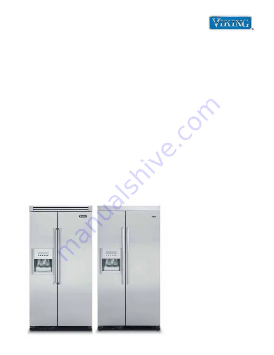
This Base Manual covers general and
VSHFL¿FLQIRUPDWLRQLQFOXGLQJEXWQRW
limited to the following models:
VCSF136D
DDSF136D
Freestanding
Side-by-Side
Refrigerator/
Freezer with
Dispenser