I N S T A L L A T I O N S H E E T
BR250/651/752 Badge Reader
www.videofied.com
Doc. - Ref. 218-BR
Version : November 2016
The BR badge reader is designed to be used within a
Videofied™ alarm system.
Its main features are :
• Interactive wireless technology.
• Dual tamper function.
• Transmits check-in/status signals every 8 minutes
• Lithium batteries : 4 years lifespan.
• Mobility-Use outdoors or indoors with a fully
weatherproof casing withstanding temperatures
from -25°C to +70°C (-13°/158°F ).
Product presentation
Installation guidelines
RF testing will ensure good communication between the
control panel and all system devices. Install the badge reader
and other system devices in the order of the following steps :
>
Program the badge reader and all other devices into the
control panel and test RF communication from each intended
device location to the control panel.
>
Mount the badge reader at the final location.
Installation and Programming
The following provides summarized steps for device programming
and testing.
1
Mount the base to the wall observing the “TOP” marking.
2
Insert 3.6V DC LS14500 Lithium batteries observing correct
polarity.
3
With the programming keypad, browse to the ADD A NEW
DEVICE menu (Level 4).
4
Press OK/YES. The keypad displays PRESS PROGRAM BUTTON
OF DEVICE.
5
Press program button. The button blinks in green. Wait for
keypad to display BADGE READER
n
RECORDED.
6
Press OK/YES. The display shows RADIO RANGE TEST?
7
Press OK/YES again to run the test. The keypad display shows
TEST IN PROGRESS.
8
Please make sure the top LED blinks in red, indicating good
communication with the control panel. The test result must stabilize at
8/9 as a minimum.
If the radio range level is below 8/9, change the location of the
detector to obtain satisfactory radio range level.
9
Press OK/YES to end the radio range test then ESC NO.
10
Choose a zone for that badge reader (by default that zone will be
delayed ) and name it.
11
The keypad displays OPERATION COMPLETED ? Mount the
badge reader on its base and press OK/YES.
12
Name the detector. When finished, keep ESC NO pressed to exit
from configuration mode.
For full programming details, please refer to the control panel
installation manual.
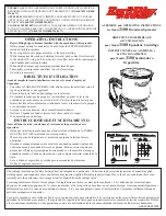
INIT
Button
Battery
Case