

PoE
After boot up, solid green indicates PoE is available.
Off indicates power supply voltage is not sufficient to
supply PoE capability. Flashing green indicates PoE
External Supply value set to 0
STATUS
Flashing blue (heartbeat) indicates power and
processor OK; off indicates no power.
Fiber Port
LEDS
(17/18)
Green. Intermittent blinking indicates valid link to
other device. Solid red indicates incompatible fiber
transceiver.
RJ45 LEDs
Amber. Intermittent blinking indicates valid link to
other device. For each pair of ports, the left LED will
show link status of the upper port while the right LED
will show status of the lower port.
Model 6716 VIA16 Ethernet Switch
Installation
Guide
6716-300-REV1
05/29/18
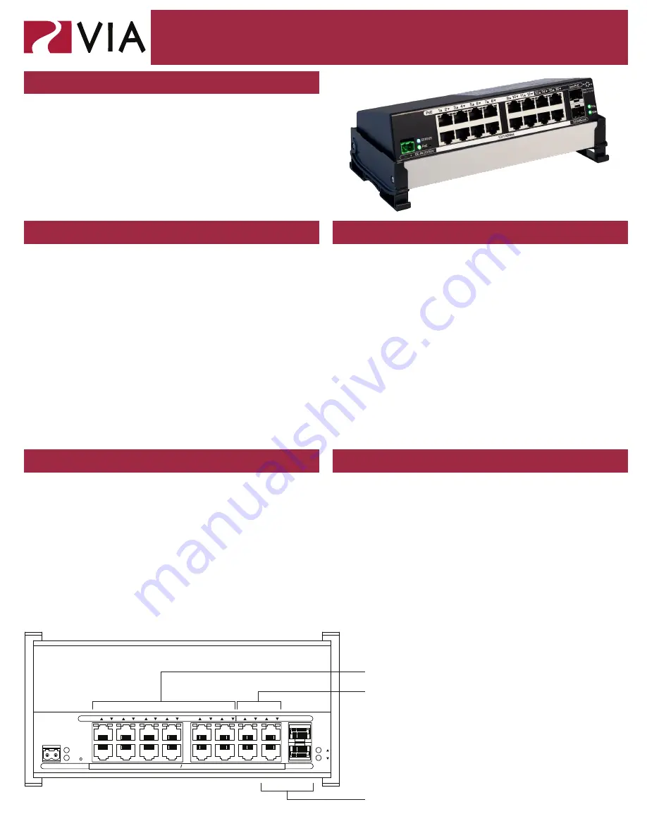
The VIA16 is a DIN-mountable, managed 10/100 Ethernet
switch with sixteen copper ports and two gigabit mini GBIC
ports for SFP modules.
This compact switch is designed specfically for sACN
data distribution and is ideal for networks usings Pathport
Gateways, Choreo controllers, Cognito consoles
and NSB or Vignette architectural wall stations, with
Power-over-Ethernet support for up to 12 devices.
POWER
The 6716 is designed to run Class 3 PoE on ports 1-12. Typically
most Pathport and Vignette devices are Class 2 or lower and a 100W
48VDC power supply (P/N 1001-100-48-DIN) will supply enough
power for the switch and 12 connected PoE devices. Observe
correct polarity when wiring DC IN plug.
ETHERNET
All network wiring should follow standard Ethernet rules and be
installed by a qualified person. As part of the installation, all wiring
should be certified under the TIA/EIA-568 standard.
Pathway recommends the use of manufactured rather than
hand-terminated cables. We also recommend 2100-DIN eDIN RJ45
patch which come in lots of 4 and use 3.5” of rail space. These
use standard punch-down female connectors and essentially build
a patch bay in the eDIN enclosure.
Disconnect all power before proceeding with installation.
Securely mount DIN rail (if not already installed in the enclosure).
Hook the upper slots on the back of the plastic extrusion to the DIN
rail and then gently but firmly press on the bottom front corners of
the extrusion to snap the module onto the rail.
Connect the DC IN terminal, after checking that polarity is correct.
The VIA16 will boot up, which may take 15-20 seconds.
Attach required network cables to RJ45 ports. Connect the fiber
module(s), if used.
The system is now ready for configuration and testing.
All field configuration of the VIA16 must be done with Pathscape
software.
Download the software from www.pathwayconnect.com and install.
Set computer’s IP to a static address in the 10.x.x.x range, with
a subnet mask of 255.0.0.0 and default gateway of 10.0.0.1. No
configuration of the computer’s DNS settings should be required.
Plug into the VIA16 and launch the software. Discovery will be
automatic.
Refer to software documentation for description of configuration
options.
OVERVIEW
CONNECTIONS
STATUS INDICATORS
INSTALLATION
FURTHER CONFIGURATION
PoE-enabled ports (1-12)
Non-PoE Ports (13-16)
EAPS Ring Protect-enabled ports
(Ethernet ports 15-16 and Fiber
ports 17-18)
Ethernet ports are numbered
top to bottom, left to right.
Top row: 1, 3, 5, 7, 9, 11, 13, 15
Bottom row: 2, 4, 6, 8, 10, 12, 14, 16
2
1
4
3
6
5
8
7
10
9
12
11
14
13
16
15
PoE
NON-PoE
- + DC IN 20-50V
10 100Mbit
1000BaseX
PoE
STATUS
18
17


