Ventrac 4200 Series, Operator'S Manual
The Eaton 4200 Series is a high-performing and reliable product designed to meet your diverse needs. Enhance your experience by downloading the user manual for free from our manualshive.com, providing comprehensive instructions and valuable information to optimize the product's functionality. Discover endless possibilities with the Eaton 4200 Series manual.
Share
Download


Reviews:
No comments
Related manuals for 4200 Series
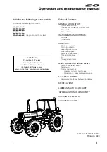
5860
Brand: LANDINI Pages: 132

RotoKnife Mini
Brand: imants Pages: 52

R 07-25
Brand: Still Pages: 246

MAXTER 50A
Brand: GOLDONI Pages: 160

TC29D
Brand: New Holland Pages: 41

Proxima Plus 90
Brand: Zetor Pages: 34

KUCS03CTBL0
Brand: KitchenAid Pages: 6

KFCK03ITWH0
Brand: KitchenAid Pages: 7

KUCK03ITBL0
Brand: KitchenAid Pages: 6

KUCS03FTPA0
Brand: KitchenAid Pages: 6

NEXUS 810
Brand: Laney Pages: 4

LL3300
Brand: LS Pages: 45

MQ600TD80
Brand: MULTIQUIP Pages: 66

MB-4 200-DF
Brand: NMC-WOLLARD Pages: 321

C8.72H
Brand: Holder Pages: 4

Park 70
Brand: Holder Pages: 87

Bluetrack
Brand: pewag Pages: 26


