

Display Systems
VDCDS P/N 790200201 / Revision 1.00
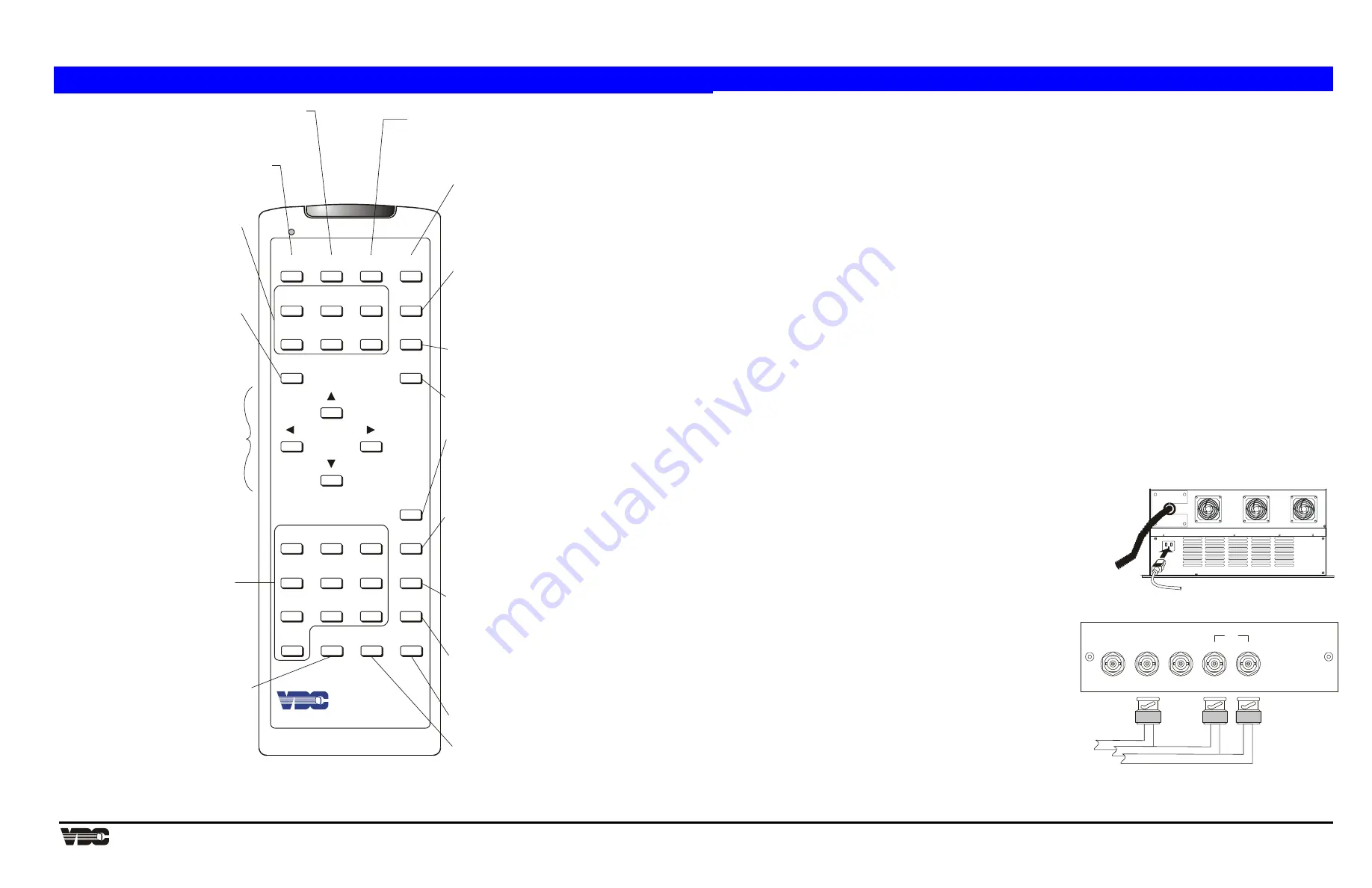
Rear View
100 - 240 VAC
50 - 60 Hz
GREEN
RED
BLUE
HOR/COMP
VERT
SYNC
Video and Sync Signals from Source
BNC
connectors
Remote Control Layout and Controls
SOURCE
1
2
3
RECALL
HELP
POWER
6
9
5
8
4
7
0
MUTE
STBY
PROJ
UTIL
PIC
GEOM
CONV
EXIT
DETAIL
VOL
TINT
BRITE
COLOR
CONT
ENTER
*
#
Picture Menu
Utilities Menu
Display Controls
Projector
Status Page
Geometry Menu
Convergence Menu
Exit
Source
Recall
Help
# Test Pattern
Mute
Numeric Keys
Enter
To adjust or set:
Phase
Size
White Balance
Focus
Sync
Blanking
Clamping
Retrace
Decoder Options
To access the following utilities:
Source Setup
Channel List
Memories Display
Preferences
To adjust:
Color
Tint
Detail
Contrast
Brightness
Volume
to command a single
projector in a multi-
projector system
to display status
pages
To adjust:
Size
Keystone
Side Pin
Top
Bottom
Bow
C Linearity
S Linearity
Skew
to adjust additional
geometry (Green)
to exit from a menu or
function
for input selection
for channel up/down selection
for source message display
to select a Recall Memory
to go back one screen during
menu/help display
to view hidden slide bars
when message display is turned off
for context sensitive help
for setup guides
to select a test pattern
for display
Power
to turn the projector on or off
Standby
to turn both picture and
audio on or off
to turn audio on or off
to turn menus on or off
for menu item selection
for number entry
to select a highlighted
menu item
to select a dialog box
option
Arrow Keys
for adjustments
for menu item selection
for movement between
edit fields
Remote Options
Clock/Events
Service
Display Systems
For Technical assistance please contact VDCDS Technical Services 321.784.4427 or [email protected]
MARQUEE
8521 Quick Start Guide
This document is intended to provide a quick-start guideline on the Marquee® 8521 Green (HUD) projector. For detailed
information refer to the User’s Manual (VDCDS P/N 71180-02) on the accompanying CD.
1.1 Quick
Setup
Follow these 5 steps for quick set up of the projector:
Step 1.
Position the Projector
To perform a quick setup, the projector must be positioned so that the throw distance is the same as that
used during the most recent optical alignment; otherwise a detailed setup is required. The throw distance is
the distance between the center lens on the projector and the center of the projection screen.
Note:
If an optical lens alignment is required, refer to Section 2.5, Optical Alignment on the accompanying
CD.
Step 2.
Connect the Power Cord
Plug the AC line cord into the line input unit on the electronic chassis. Plug the three prong end of the line
cord in a grounded AC outlet.
Note:
Input voltage must be between 90 VAC and 264 VAC.
Note:
Ensure the line cord is the proper type for the AC receptacle.
Step 3.
Connect a Source
Connect a source to the projector's built-in RGB input (slot 1). Ensure the source is on and properly
connected. Refer to Section 1.2 and Figure 1 below.
Step 4.
Turn the Projector On
Hold down the [
POWER
] on the keypad for one second to turn the projector on.
Note:
If the keypad has been configured for IR remote operation, point it towards the screen or the front of
the electronic chassis.
Step 5.
Select the Input
Press
[
SOURCE
] [
0
] [
1
] to select the source connected to the built-in RGB input.
Adjust the Display; Press [
HELP
] [
1
] to select the Guided Source Setup tutorial.
1.2 Source Connections
To apply power to the projector, plug the AC line cord into the line input socket
located at the rear panel of the electronic chassis. Plug the three prong end of
the line cord in a grounded AC outlet. Input voltage to the projector must be
between 90 and 264 VAC, 50 or 60 Hz. The power source must supply 650
watts of power to the projector.
The projector includes a built-in RGB input interface (Video Input Module) for
connection of external RGB sources. This input interface is shown in Figure 1.
The built-in interface is required for normal operation.
The standard RGB interface is typically used for connection of a
R
ed
G
reen
B
lue
source having one of the following sync types: sync on
green (3-wire), composite sync (4-wire), or separate H & V sync (5-
wire).
The Marquee® HUD Series is a specialized projector utilizing a single
input or color. In this case, connect the source to the GREEN input on
the interface. If the source uses sync on green, no additional cables
are required. If the source provides a composite sync output, connect it
to the HOR/COMP input. If the source provides separate horizontal
and vertical sync outputs, connect the horizontal sync signal to the
HOR/COMP input, and connect the vertical sync input to the VERT
input. Interconnection cables must be terminated with BNC connectors.
Figure 1 shows the source connections for the built-in interface.
Figure 1. AC and Source (Green) Input Connections.
NOTE:
This document is intended to be printed on 11 x 17, double sided


