Varta element 6, Operating Manual
The Varta Element 6 Instruction Manual is available for free download on our website. With this comprehensive manual in hand, you can effortlessly set up and operate your Varta Element 6 device. Find all the necessary information, troubleshooting tips, and handy instructions to optimize your user experience from manualshive.com.
Share
Download


Reviews:
No comments
Related manuals for element 6
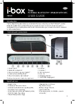
Trax
Brand: i-box Pages: 4

WR-11BT
Brand: Sangean Pages: 13

HL2022A
Brand: bem wireless Pages: 5

SRP9170
Brand: Simoco Pages: 50

TI4676
Brand: Tesla Pages: 37

P1000i
Brand: P1PE Pages: 32

SPSBTB14E
Brand: Sandstrom Pages: 140

DVD8006
Brand: Curtis Pages: 15

PD7032T
Brand: Philips Pages: 22

PD704
Brand: Philips Pages: 24

PD9005
Brand: Philips Pages: 27

PD9010
Brand: Philips Pages: 30

PD9003
Brand: Philips Pages: 32

MS-510
Brand: Millenium Signatures Pages: 7

GEN3500i
Brand: Sportsman Pages: 30

DP770
Brand: Kirisun Pages: 46

38862
Brand: Chicago Electric Pages: 13

840 LZR
Brand: Panacom Pages: 13


