©Vantage, 8/10/2016 / IS-0496-B
Standard Low Voltage Keypad — MODEL: KS1XXX-XXXX
page 1 of 2
I N S T A L L A T I O N
V A N T A G E C O N T R O L S . C O M
V A N T A G E I N S T A L L G U I D E S
2168 West Grove Parkway, Suite 300, Pleasant Grove, UT. 84062 USA
Telephone: 801 229-2800
●
Fax: 801 224-0355
Standard Low Voltage Keypad — MODEL: KS1XXX-XXXX
Overview
The Vantage Keypad Station is one of the primary control
points of a Vantage System. Standard features include 2 color
LEDs, sounders, and a variety of faceplate designs, colors and
finishes. Select a button style from two different designs;
FineTouch or SquareTouch, (see note for EasyTouch II and RP-
Touch*). An optional built in IR receiver is available on most
models. An auxiliary 6-wire connection on the back of each
keypad is provided for easy connection of external devices
(e.g., external IR receivers, dry-contacts, motion detectors,
light sensors, etc.). Keypads and their faceplates can be
ordered in multiple gang configurations including third party
devices utilizing Decora punch and other designs. See InFusion
Design Center software for a complete selection.
*NOTE: Please see install sheets IS-0464 for RP-Touch and IS-
0533 for EasyTouch II, 3-color, low voltage keypads.
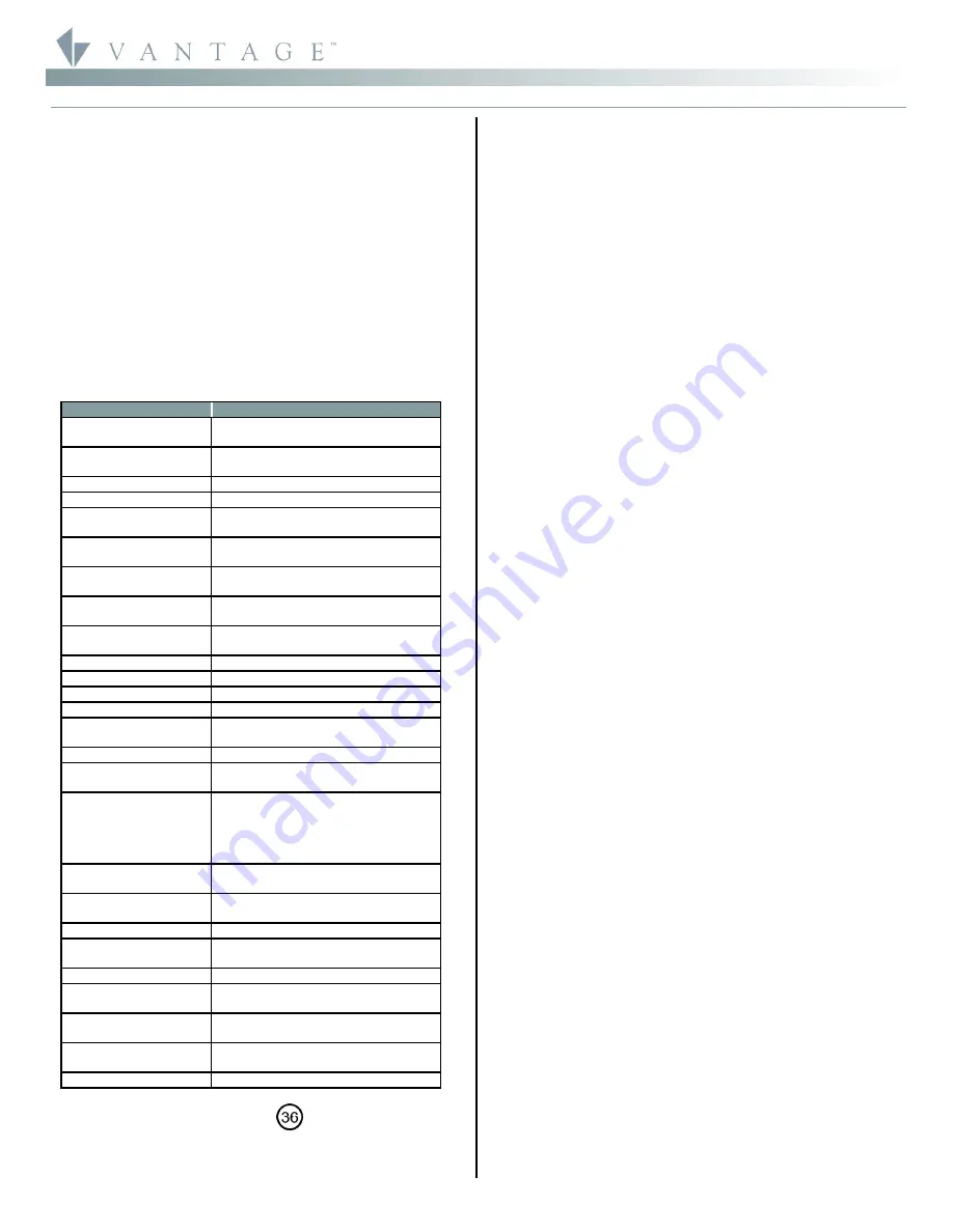
Specifications
Description
Specification
Dimensions, HWD
4.75” x 2.9” x .875”
121mm x 74mm x 22mm
Finished
Single Gang
Approx. Weight
Metal Face Plate 6.5 oz. or 184g
Plastic Face Plate 3.7 oz. or 105g
Power
24V/36V DC via Station Bus
Surge Suppression
Yes
Maximum Number of
Buttons
8
Maximum Number of
Auxiliary Connections
2
Maximum Number of
Stations per Master
50
Maximum Number of
Gangs
Metal up to 5-gangs
Plastic up to 4-gangs
LED
Red/Green
Red/Blue
IR Option
Yes
Sound Option
Yes (variable pitch)
Wiring Connection
2 Wire 600V Pigtail (included)
Addressing
Self addressing through software
Power for External
Devices
15 mA @ 12V DC
Polarity Sensitive
No
Station Wiring
configuration
Daisy-chain/Star/Branch
Station Bus
Specification
2C, 16AWG / 1.31mm2, twisted, non-
shielded, <30pF per foot. Separate a
minimum of 12" / 30.5cm from other
parallel communication and/or high
voltage runs.
Station Equivalent
InFusion – 8 button
0.82W on IC-24 / 1.22W on IC-36
Station Equivalent
InFusion – 4 button
0.72W on IC-24 / 1.08W on IC-36
Equivalent QLink
1 Station on QLink Main Controller
Station Bus
connections*
24V / 36V Station Bus
Finishes See
Below
Ambient Operating
Temperature
32-95°F -or- 0-35°C
Ambient Operating
Humidity
5-95% non-condensing
Outdoor Use
With Approved Weatherproof Cover
(WPC-1 or WPC-2)
UL and CUL Listed
Yes
*CAUTION:
36V stations have a
symbol on the Serial
Number sticker. Any station, not displaying this symbol, should
not be connected to a 36Volt Station Bus.
System Requirements
This station is compatible with InFusion Design Center
software and QLink Software. For new projects it is
recommended that firmware and software be kept to the most
current release.
Installation
Installation of Vantage products should be performed or
supervised by a
Certified Vantage Installer.
The Vantage
Keypad Station installation is very simple. Connect using the 2
wire pigtail connection located on the rear of the station.
It can be mounted into a standard 1-5 gang electrical box for
some Metal faceplates or 1-4 gang electrical box for Plastic
faceplates.
Standard Keypad Set Up In Software
InFusion:
Starting a new project, first in the
Project Explorer
click on
Style/Profile View
. Right click on
Keypad Styles
and
select
Add Keypad Style
. In the
Object Editor
window fill in all
the information for the keypad style. While still in Style/Profile
View, right click on
LED Styles
and fill in the appropriate
information in the Object Editor for desired LED settings. Next
select the room, then click on
Vantage Objects
in the
Object
Explorer
and expand
Stations, WireLink
. From the list of
stations double click on Keypad Station to place it in the room.
In the
Object Editor
name the station, make sure it is on the
correct station bus port and make any other modifications.
Right click on the keypad or buttons in the
Object Editor
for
additional settings.
Configuration
When the station is first connected to the Station Bus, the
diagnostic LED will blink twice followed by a pause, meaning
that the station is connected correctly but not yet configured.
From Design Center, click on the Configure Stations button on
the toolbar. Highlight the station. The Status LED will blink 5
times followed by a pause and the button LEDs will blink
rapidly indicating that the station is in configuration mode. To
finish configuring press any button on the Station 3 times. The
station may also be configured by typing the serial number in
the project file, using this method the station will automatically
be configured when the system is programmed. Please note, if
the serial number contains an alpha character please ignore
this when typing in serial number. Once configured the Status
LED will be off and the buttons stop blinking.
Auxiliary Connections
All auxiliary connections to the station are wired to a pigtail
available from Vantage. Motion detectors, wood and metal
door contacts, light sensors, etc., are available from Vantage
and work by simply connecting them to the Auxiliary
connector. The aux. connection includes power sufficient for
most connected sensors. The aux. power supply is 15mA @ 12V
DC.
Diagnostic LED Information
If the faceplate is removed the Status LED can be seen in the
middle of the station’s switch matrix. The Status LED blinks
evenly or flashes 2, 3, 4 or 5 times followed by a pause to
indicate status information.
Off: The station is not powered. A Station Bus connection has
not been made or the Main Controller is not powered.
One Even blink: Station is operating correctly and is
configured.
Two blinks: Station is operating correctly but is not
configured.
Three blinks: Station is
not
communicating with the Main
Controller. Verify that station bus wiring is correct and
conforms to Vantage guidelines.
Four blinks: station problem. Please contact the factory.