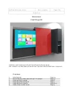
background image


Installation


needs


to


be


done


according


to


the


sketch


given


by


the


sales


people

After


installation


of


profiles


please


proceed


with


level


o

panels


and


afterwordswith


level

1


components

Overview:

1.

Attaching


rails

Page


2

4

2.

Mount


the


side


profiles


and


endstops*


(*if


ordered)

Page


5

7

3.

Placement


level

0


panels

Page


8

4.

Placement


of


level

1


boards

Page


9

5.

Placement


level

2


boards

Page


10

13

6.

Cable


entries


(custom


made)

Page


14

HL

Momentum

0001

12

04

A

Date


:


21/03/2013

Page


1


of


14


Momentum


Momentum

Assembly


guide

Summary of Contents for Momentum

Page 1: ...wordswith level 1 components Overview 1 Attaching rails Page 2 4 2 Mount the side profiles and endstops if ordered Page 5 7 3 Placement level 0 panels Page 8 4 Placement of level 1 boards Page 9 5 Pla...

Page 2: ...dwalls is not included Hold the rail against the wall and mark the holes in the profile by using a laser beam Distance between floor and hole marks is 940mm 37 Drill the holes in the wall and fix with...

Page 3: ...all and mark the holes in the profile by using a laser beam Vertical distance between holes in the rails is 1075 42 21 64 Drill the holes in the wall and fix with hardware plugs and screws for solid w...

Page 4: ...th the sides in line and mark the holes Remove rail and plates and drill holes on the marks Fix the top rail position of distance plates d Click the cover profile into the top rail cover profile color...

Page 5: ...es If ordered slide the end stop s in the top rail necessary when combining level 2 board s with cabinet s see page slide the connectors in the rails top below Momentum HL Momentum 0001 12 04 A Date 2...

Page 6: ...e body of the connector in line with the end of the rail and fix the connector bottom view insert the end cap install the side profile HL Momentum 0001 12 04 A Date 21 03 2013 Page 6 of 14 Momentum in...

Page 7: ...place the end profile against the rails and slide it down in the connectors Fix the side profile with an allen wrench in short staps Date 21 03 2013 Page 7 of 14 Momentum HL Momentum 0001 12 04 A...

Page 8: ...anel above the gap in the lower rail and let the panel sink in it example backpanel i touchscreen 70 module 8 slide the panel to its correct position and turn the adjusters sitting in the back of the...

Page 9: ...Placement of level 1 boards and cabinets Hang the board or cabinet to the rail top below top below HL Momentum 0001 12 04 A Page 9 of 14 Momentum Date 21 03 2013...

Page 10: ...right 2 3 Top bracket left 2 4 Lower bracket 2x a Top bracket Place the top brackets in the corner of the board with the trapezium shaped nut in its open position Page 10 of 14 Momentum HL Momentum 00...

Page 11: ...se under the boardprofile and fix it by fastening the screw open position of the nut closed position of the nut nut colored black correctly placed between the board profile HL Momentum 0001 12 04 A Da...

Page 12: ...with the trapezium shaped nuts in their open position Turn the trapezium shaped nuts clockwise under the boardprofile and fix it by fasten the screws open position of the nuts closed position of the n...

Page 13: ...rail detail upper side detail lower side Fix the end stop so that there is a little space between the board and the cabinet HL Momentum 0001 12 04 A Date 21 03 2013 Page 13 of 14 Momentum top view ca...

Page 14: ...ap between wall and level o or level 1 example cut out in the top rail for wires running to a short throw beamer gable grommel allows cables to pass trough behind level 0 or level 1 boards HL Momentum...

Reviews: