


Reviews:
No comments
Related manuals for POWERCOM 485

LRA-900
Brand: ICP DAS USA Pages: 21

EXI 01
Brand: Kathrein Pages: 16

08-15356
Brand: Zoom Pages: 36

433NW30
Brand: Ebyte Pages: 18

433C33
Brand: Ebyte Pages: 18

433L20
Brand: Ebyte Pages: 18

900SL30-ETH
Brand: Ebyte Pages: 24

GEN-127
Brand: Genesis Pages: 3

TC4300
Brand: Flash Pages: 2

IBOS Cellular Modem
Brand: Philadelphia Scientific Pages: 16

P.DG A4001N
Brand: ADB Pages: 108

9600 BPS
Brand: FAX Pages: 6

TFM-560PCI
Brand: TRENDnet Pages: 44
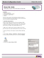
DSL-504G
Brand: D-Link Pages: 5

LandCell 819?1XRT
Brand: CalAmp Pages: 14

KAM
Brand: Kantronics Pages: 55

OV303R2M
Brand: Ovislink Pages: 17

Skyus 3G Sprint
Brand: Feeney Wireless Pages: 11


