


MicVIEW
™
Teleconference Microphone Switcher/Mixer
The Vaddio MicVIEW is the microphone switching unit for use in an automated
camera positioning system or in a stand alone operation. The MicVIEW has twelve
microphone inputs with 24V phantom power and +5V status line outputs. Micro-
phones one and two can disable the phantom power and switch between mic-level
and line-level inputs such as cordless, lapel microphones.
• Carefully remove the device and parts from the packing material.
• Set the unit on a flat, solid surface. Unpack and identifiy the following parts:
– One, power supply
– Eighteen, 3-position female 5mm screw terminals
Introduction
MicVIEW
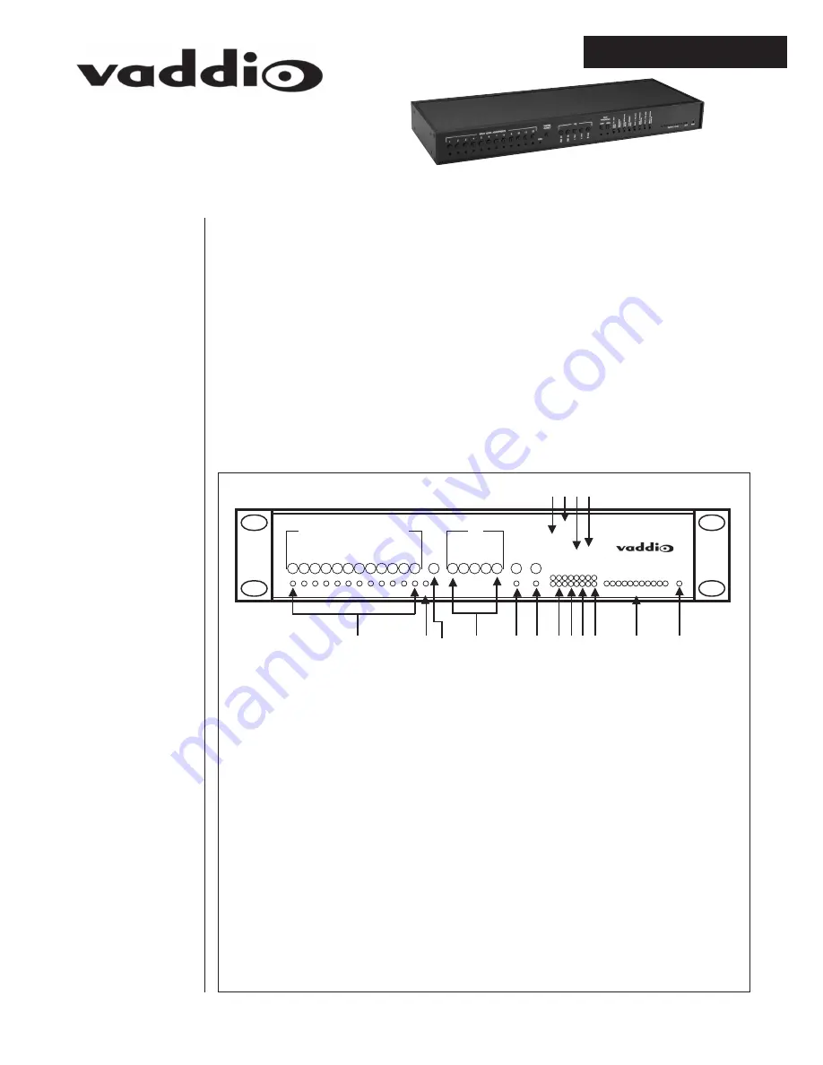
Front Panel
Unpacking
Your
MicVIEW
(1) POWER INDICATOR – Green LED indicates that 12 VDC has been connected.
(2) OUTPUT LEVEL – VU Meter indicating volume with CLIP indicator.
(3) INPUT 2 PHANTOM POWER – Toggles Phantom Power on Input 2.
(4) INPUT 2 MIC BUTTON – Toggles Line-Level and Mic Level on Input 2.
(5) INPUT 1 PHANTOM POWER – Toggles Phantom Power on Input 1.
(6) INPUT 1 MIC BUTTON – Toggles Line-Level and Mic-Level on Input 1.
(7) MUTE BUTTON – Mutes microphones 2-12 only.
(8) FORCE INSTRUCTION MIC ON – Mixes microphone 1 with one of the other microphones 2-12 at all
times.
(9) INSTRUCTOR PRIORITY – Gives the instructor the ability to take control from the other micro-
phones.
(10) PUSH-TO-TALK MODE – Toggles between Push-To-Talk and Voice Activated.
(11) HIGH GATE THRESHOLD – Adjusts the threshold at which the Voice Activated function can trigger
from microphone.
(12) LOW GATE THRESHOLD – Adjusts the trigger at which the Push-To-Talk function can be triggered.
(13) EQ – Adjusts the gain of certain frequencies of the output.
(14) MASTER OUTPUT – Adjusts the output gain of the entire MicVIEW system.
(15) LINK LIGHT – Indicates that the system is linked to additional MicVIEW systems.
(16) INPUT LEVLE ADJUSTMENTS – Adjusts the gain of specific microphone inputs.
AUDIO LEVEL
PUSH-TO-TALK MODE
INSTRUCTOR PRIORITY
FORCE INSTRUCTION MIC ON
LINK UNITS
INPUT 1 MIC
INPUT 2 PHANTOM POWER
INPUT 2 MIC
INPUT 2 PHANTOM POWER
1
2 3 4
5 6
7 8 9 10 11 12
1
2 3 4
5
INPUT LEVEL ADJUSTMENTS
EQ
MASTER
OUTPUT
LOW
HIGH
GATE
THRESHOLD
PWR
LINK
CLIP
1
2
3
5
7
9
13
11
12
14
15
16
10 8 6 4
1
Installation & User Guide


