

-1-
-2-
-3-
-4-
1 Packing List
Please check the following items after unpacking, if any missing, please
contact your local dealer.
No.
Items
Quantity
1
Switch
1 pc
2
AC Power Cable
1 pc
3
Mounting Accessory
1 set
4
Quick Installation Guide
1 pc
2 Safety Information
Before performing an operation, read the following operation instructions
and precautions to be taken, and follow them to prevent accidents.
2.1 General Requirements
Only qualified and skilled personnel must install, configure, and
unmount the device. The device must not be disassembled.
When operating the device, obey the local safety regulations. The
safety precautions provided in the document are supplementary and
shall be in compliance with the local safety regulations.
When operating the device, in addition to the precautions (please see
the notes below), follow the specific safety instructions.
The installation and maintenance personnel need to understand the
basic safety precautions to be taken.
Do not block the ventilation while the device is running. Keep a
minimum distance of 5 cm from the ventilation to the walls or the other
objects that block the ventilation.
Do not operate the device in an area that exceeds the maximum
recommended ambient temperature of 50°C.
Do not place the device in the environment that has inflammable and
explosive air or fog. Do not perform any operation in this environment.
2.2 Electric Safety
During the installation of the AC power supply facility, follow the local
safety regulations. The personnel who install the AC facility must be
qualified to perform high voltage and AC operations.
Before touching the device or hand-operating parts, wear a grounded
electrostatic discharge (ESD) wrist strap. It can prevent the sensitive
components from damage by the static electricity in the human body.
2.3 Optical Safety
When handling optical fibers, do not stand close to, or look at the
optical fiber outlet directly with unaided eyes.
Cutting and splicing fibers must be performed by the trained personnel
only.
Before cutting or splicing a fiber, ensure the fiber is disconnected from
the optical source. After disconnecting the fiber, use protecting caps to
protect all the optical connectors.
3 Product Introduction
3.1 Overview
The product is 8-Port Gigabit PoE+ 1-Port Gigabit RJ45 1-Port Gigabit
SFP L2 Managed Ethernet Switch.
This switches provide 8*10/100/1000Mbps Ethernet RJ-45 ports,
1*10/100/1000Mbps Ethernet RJ-45 uplink port, 1*1000Mbps SFP uplink
port. It meets IEEE 802.3af/at standard. All downlink RJ-45 ports support
Power-over-Ethernet (PoE+), which can deliver up to 30W power per port.
The switch has extensive L2 management functions, such as static routing,
802.1Q VLAN, IGMP, QoS, ACL, DHCP Snooping, ARP and Telnet. It can
be easily managed via a WEB GUI, CLI (telnet/console), or SNMP. It can
be widely used in video security monitoring system, network project, etc.
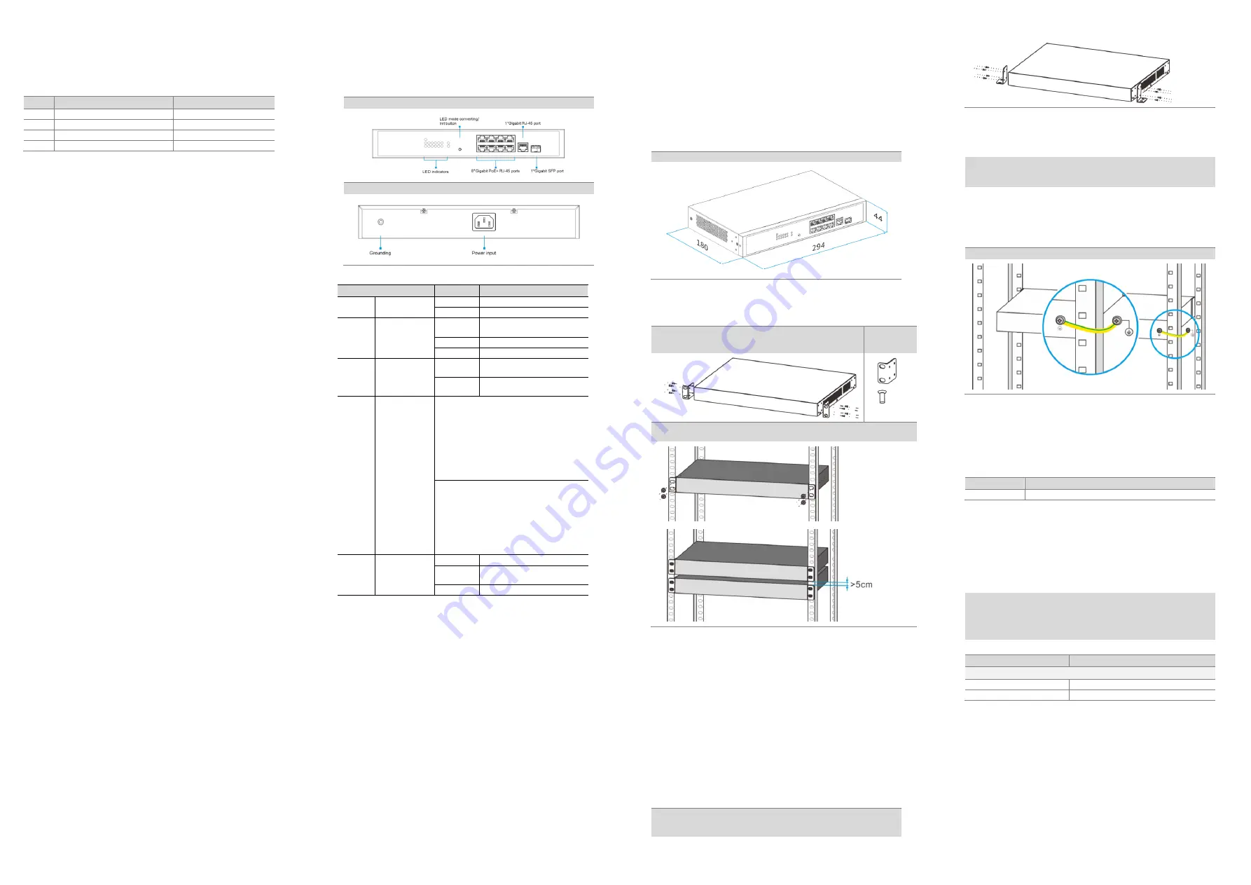
3.2 Hardware Introduction
Front Panel
Rear Panel
Led Indicators Instructions
Indicators
Status
Descriptions
Power
Power supply
indicator
Solid on
Power Supply is on.
Off
Power Supply is off.
SYS
System working
indicator
Solid on
The system is not working
normally.
Blink
The system works normally
Off
No PoE Power output.
PoE-Ma
x
PoE power
indicator
Solid on
The total power of the switch
reaches the max value.
Off
The total power of the switch
does not reach the max value.
Link or
PoE
Port state
indicator
(multipurpose)
When the Link LED indicator of LED mode is
solid on, the Link/Act or PoE LED indicator is in
the Link/Act mode :
Solid on: The port is linking normally.
Blink: The port is transmitting or receiving data.
Off: The port links down.
Green light indicates that negotiation rate of
the port is 1000Mbps, orange light indicates a
rate of 10 or 100Mbps.
When PoE LED indicator of LED mode is solid
in ,the Link/Act or PoE LED indicator is in the
PoE mode :
Solid orange: The port is supplying PoE power
normally.
Blink orange: The port is not supplying PoE
power normally.
Off: The port stops supplying PoE power.
Link
Port state
indicator
Solid on
The port is linking normally.
Blink
The port is transmitting or
receiving data.
Off
The port links down.
Link or PoE mode/Init Button
The multipurpose button is for LED indicator converting and reset.
By short pressing the button about 2s, the LED mode will be switched
between Link mode and PoE mode.
By pressing the button over 5s, the switch will be restored to the
original factory default setting.
4 Installations
This series switch supports three installation modes:
Rack mounted installation
Desktop installation
Wall mounted installation
The dimension of this series is the same in terms of switches and
accessories.
Dimensions (mm)
4.1 Rack Mounted Installation
This switch supports
19” rack mounted installation. Following with the
installation steps below.
Step1: Fix the provided rack mounted hangers to the left and right
side of the device using 4 screws each. Use the four holes on the
left and right side of the device.
Accessories
2*
8*
Step 2: Install the switch to the rack.The distance between the devices in the rack
should be more than 5cm.
4.2 Desktop Installations
This series of switches support desktop installation. Users can put this
product on clean, stable, grounded workbench.
Please follow the steps below:
Carefully put the device upside down, clean the grooves on the chassis
backplane with soft cloth to make sure there is no oil or dust in it.
Remove the stickers on the foot pad, paste the foot pad on the four
corners at the bottom of the switch.
Carefully put the device upright on the workbench.
4.3 Wall-mounted Installations
Drill 4 holes on the wall where the device is installed according to the
dimensions of the switch and accessories. Insert an expansion anchor into
each hole drilled in the wall, and beat the top of it with a rubber hammer
until all the anchor is inserted into the wall.
Please follow the steps below:
Fix the provided rack mounted hangers to the left and right side of the device
using 4 screws each. Use the four holes on the left and right side of the device.
Fix to the switch to the wall.
5 Connect the Power Supply
Note:
Ground the switch housing with the grounding screw on the side of the housing!
Always make the ground connection first and disconnect it at the end.
Use one end of PGND cable to connect the M4 grounding connector of the
switch, the other end to a ground point. The PGND of the switch is shorted
to the copper protection ground bar provided by the user. The PGND cable
used should be an alternating yellow and green plastic insulating one with
copper core, with cross-sectional area greater than 2.5mm².
The figure below takes rack-mounted installation as example.
Ground the switch housing
This series switch supports 100~240V AC power supply.
100~240V AC Supply
Use an AC power cable to connect the AC power connector of the switch.
It is recommended to use the AC power cable provided in the package.
Connect the mains supply to the building’s power supply network.
Please observe the following specifications:
Items
Specifications
Input Voltage
100~240V AC, 50~60Hz
5.1 Starting Up
After connection to the power supply, the switch starts automatically. LED
indicators “PWR” turns green, and after about 90s, the system is ready.
6 Factory Settings
Note:
Please note that the factory settings may change with future firmware versions.
For this reason we recommend that you check the release notes for information
about any changes to the factory settings before carrying out a firmware
update.
The switch starts with its factory settings:
Items
Specifications
IP Configuration
Default Static IP Address
192.168.1.200
Default Subnet Mask
255.255.255.0
7 Access Network Management
After starting up successfully, connect the switch to your local network
segment using a suitable cable to access the switch network management
system. For details, please refer to the following document:
Web Configuration Guide
Describes Web network management system configuration instructions.


