3100 Series™ is a registered trademark of UTC RETAIL
11692017 Rev A
2009 UTC RETAIL. All rights reserved.
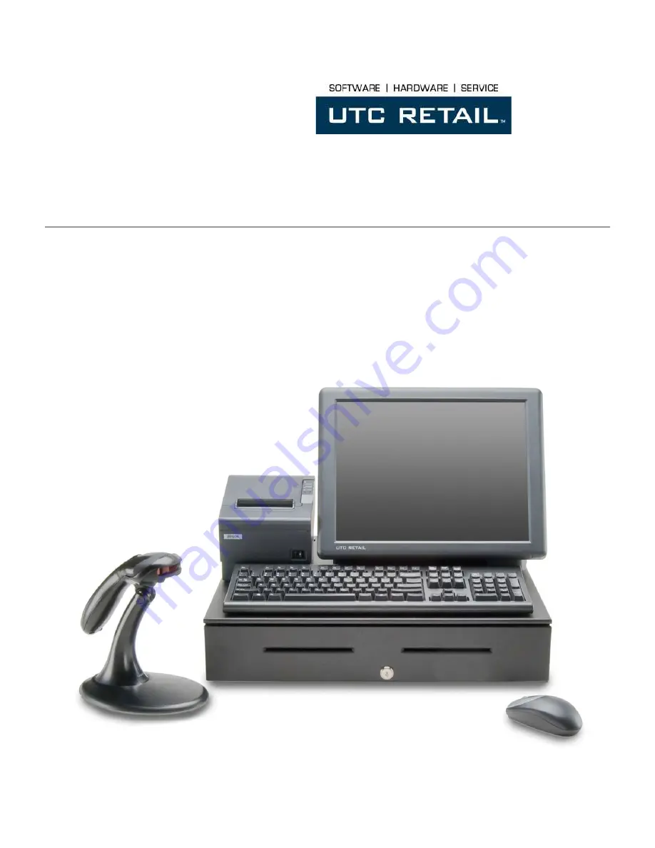
3100 Series POS Bundle
3100 Series POS Bundle Installation Guide
Thank you for selecting UTC RETAIL’s innovative 3100 Series Point of Sale bundle solution!
This guide is designed to help you efficiently assemble the 3100 Series POS Bundle System.