background image

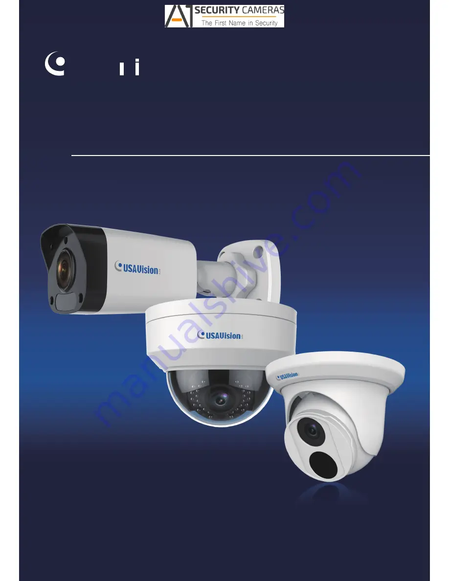
UVS-ABD1300, UVS-ABL1300, UVS-ADR1300 

User's Manual


Before attempting to connect or operate this product, 

please read these instructions carefully and save this manual for future use. 

UVS1300V10

1

-A


                    Available from A1 Security Cameras 

    www.a1securitycameras.com email: [email protected]

Summary of Contents for UVS-ABD1300

Page 1: ...Manual Before attempting to connect or operate this product please read these instructions carefully and save this manual for future use UVS1300V101 A Available from A1 Security Cameras www a1securitycameras com email sales a1securitycameras com ...

Page 2: ... damages arising from the use of the information or products contained herein Features and specifications are subject to change without notice Note No memory card slot or local storage function for Argentina USA Vision Systems Inc 9235 Research Drive Irvine CA 92618 USA Tel 1 949 583 1519 Fax 1 949 583 1522 http www usavisionsys com Trademarks used in this manual USAVision the USAVision logo and U...

Page 3: ...ng models and firmware versions Model Model Number Firmware Version Eyeball Dome ABD1300 V1 01 Bullet IP Camera ABL1300 Mini Fixed Rugged IP Dome ADR1300 Available from A1 Security Cameras www a1securitycameras com email sales a1securitycameras com ...

Page 4: ...ng the Dynamic IP Address 7 2 1 2 Assigning an IP Address 9 2 2 Accessing Live View 11 2 2 1 The Live View Window 12 Chapter 3 Administrator Mode 15 3 1 Common 17 3 1 1 Basic Info 17 3 1 2 Local Settings 18 3 2 Network 20 3 2 1 Network 20 3 2 2 DNS 22 3 2 3 Port 23 3 2 4 FTP 25 3 2 5 E mail 27 3 3 Video 28 3 3 1 Video 28 3 3 2 Snapshot 30 3 3 3 Media Stream 31 3 4 Image 33 3 4 1 Image 33 3 4 2 OSD...

Page 5: ...erface 57 5 1 2 Using the GV IP Device Utility 58 5 2 Restoring to Factory Default Settings 60 5 2 1 Using the Web Interface 60 5 2 2 Directly on the Camera 61 Chapter 6 DVR Configurations 62 6 1 Setting Up IP Cameras on GV System 63 6 1 1 Customizing the Basic Settings on GV System 65 6 2 Setting Up IP Cameras on GV VMS 66 Appendix 68 A RTSP Protocol Support 68 B Optional Installation for ABD1300...

Page 6: ...Software The GV System also refers to Multicam System GV NVR System GV DVR System and GV Hybrid DVR System at the same time GV VMS GeoVision Video Management System for IP cameras Available from A1 Security Cameras www a1securitycameras com email sales a1securitycameras com ...

Page 7: ...m Once the cameras are connected to the GV VMS DVR NVR the resolution set on the GV VMS DVR NVR will override the resolution set on the cameras Web interface You can only change the resolution settings through the Web interface when the connection to the GV VMS DVR NVR is interrupted Available from A1 Security Cameras www a1securitycameras com email sales a1securitycameras com ...

Page 8: ... periodically if you seldom access the memory card 3 Memory cards are expendable and their durability varies according to the conditions of the installed site and how they are used Back up your data regularly and replace the memory card annually 4 To avoid power outage it is highly suggested to apply a battery backup UPS 5 For better performance it is highly suggested to use Micro SD card of MLC N...

Page 9: ... prevent water from entering the camera along the cables 2 Any power audio and I O cables are waterproofed using waterproof silicon rubber or the like 3 The screws are tightened and the cover is in place after opening the camera cover Available from A1 Security Cameras www a1securitycameras com email sales a1securitycameras com vii ...

Page 10: ...Available from A1 Security Cameras www a1securitycameras com email sales a1securitycameras com ...

Page 11: ... and 2 IR LEDs for day and night surveillance The camera adheres to IP66 standards The Bullet Camera offers an entry level surveillance solution with all the essential features at excellent image quality For ADR1300 The Mini Fixed Rugged Dome is an outdoor fixed network camera equipped with an automatic IR cut filter and 30 IR LEDs for day and night surveillance The camera adheres to IP66 and IK10...

Page 12: ... tolerance 35 C 60 C 31 F 140 F DC 12V PoE IEEE 802 3af Wide Dynamic Range WDR Defog 3D noise reduction Motion detection Text overlay Privacy mask ONVIF Profile S conformant For ABL1300 1 3 progressive scan low lux CMOS sensor Min illumination at 0 06 lux B W and color Triple streams from H 264 and MJPEG Up to 30 fps at 1280 x 960 Intelligent IR IR distance up to 30 m 98 4 ft Day and night functio...

Page 13: ...0 x 960 Intelligent IR IR distance up to 30 m 98 4 ft Day and night function with removable IR cut filter 3 axis mechanism pan tilt rotate Ingress protection IP66 Vandal resistance IK10 Wide temperature tolerance 35 C 60 C 31 F 140 F Built in micro SD card slot SD SDHC SDXC UHS I Class 10 for local storage DC 12V PoE IEEE 802 3af Wide Dynamic Range WDR Defog 3D noise reduction Motion detection Tex...

Page 14: ... Camera Waterproof Rubber Set Screw x 5 Screw Anchor x 5 Drill Template Paster Software Download Guide Warranty Card For ADR1300 Mini Fixed Rugged IP Dome Waterproof Rubber Set Screw x 3 Screw Anchor x 3 Drill Template Paster Torx Wrench Software Download Guide Warranty Card Available from A1 Security Cameras www a1securitycameras com email sales a1securitycameras com ...

Page 15: ...sions 93 x 93 x 39 mm 3 66 x 3 66 x 1 53 Weight 0 235kg 0 52 lb Only ABL1300 supports this accessory GV PA191 Power over Ethernet PoE Adapter The GV PA191 is a Power over Ethernet PoE adapter designed to provide power to the IP device through a single Ethernet cable GV POE Switch The GV POE Switch is designed to provide power along with network connection for IP devices The GV POE Switch is availa...

Page 16: ...ower will be provided over the network cable 3 You can now access the Web interface of the camera If the camera is installed in a LAN with the DHCP server use GV IP Device Utility to look up the camera s dynamic IP address See 2 1 1 Checking the Dynamic IP Address If the camera is installed in a LAN without the DHCP server the default IP address 192 168 0 10 will be applied To assign a different s...

Page 17: ...ed with GV IP Device Utility must be under the same LAN with the camera you wish to configure 2 On the GV IP Utility window click the button to search for the IP devices connected in the same LAN Click the Name or Mac Address column to sort Figure 2 1 3 Find the camera with its Mac Address click on its IP address and select Web Page Figure 2 2 Available from A1 Security Cameras www a1securitycamer...

Page 18: ...For the first time accessing the Web interface download and install the plug in 6 Type the default ID and password admin and click Login to login Available from A1 Security Cameras www a1securitycameras com email sales a1securitycameras com ...

Page 19: ... IP address to avoid the IP address conflict with other GV IP devices on the same LAN 1 Open your web browser and type the default IP address http 192 168 0 10 A dialog box appears 2 Type the default username and password admin Click Login 3 Click Setup select Common in the left menu and select Ethernet Figure 2 4 4 Select Static IP from the IP Obtain Mode drop down list Available from A1 Security...

Page 20: ...etwork 6 Click Save Note When you are changing the network segment through the Web interface or the GV IP Device Utility V8 7 0 0 it is required that you change the default gateway too to complete the IP address change successfully Available from A1 Security Cameras www a1securitycameras com email sales a1securitycameras com ...

Page 21: ... 2 Accessing Live View After logging in to your camera you will see the Home page as shown below Figure 2 5 Available from A1 Security Cameras www a1securitycameras com email sales a1securitycameras com ...

Page 22: ...b stream or third stream 3 Image Open the image setting page See 3 4 1 Image 4 Full Screen Mode Display in full screen mode 5 Play Stop Play or stop live video 6 Snapshot Take a snapshot of the current image displayed on the PC 7 Local Recording Start or stop local recording 8 Digital Zoom Start or stop digital zoom See 2 2 1 1 Digital Zoom 9 Reset the packet loss rate to zero Available from A1 Se...

Page 23: ...e mouse cursor on a live view window 3 Click the button No 10 to display the bottom information Click this button again the bottom information is displayed if the mouse cursor is moved on a live view window or on the bottom information and it hides automatically if the mouse cursor remains on a live view window for 3 seconds or leaves the window Available from A1 Security Cameras www a1securitycam...

Page 24: ...lick and hold the mouse button and then drag from the top down to specify an area 3 To restore the original image size click in the enlarged area or drag from the bottom up 4 To exit click No 8 Figure 2 6 on the toolbar Available from A1 Security Cameras www a1securitycameras com email sales a1securitycameras com 14 ...

Page 25: ...ra through the network Click Setup at the top of the Web interface to access the following seven configuration tabs Common Network Video Image Events Storage Security and System Figure 3 1 Available from A1 Security Cameras www a1securitycameras com email sales a1securitycameras com ...

Page 26: ... 1 Basic Info 3 1 2 Local Settings 3 2 Network 3 2 1 Network 3 2 2 DNS 3 2 3 Port 3 2 4 FTP 3 2 5 E mail 3 3 Video 3 3 1 Video 3 3 2 Snapshot 3 3 3 Media Stream 3 4 Image 3 4 1 Image 3 4 2 OSD 3 4 3 Privacy Mask 3 5 Events 3 5 1 Motion Detection 3 6 Storage 3 6 1 Storage 3 7 Security 3 7 1 User 3 7 2 Network Security 3 8 System 3 8 1 Time 3 8 2 Maintenance Available from A1 Security Cameras www a1...

Page 27: ...ime for details OSD See 3 4 2 OSD for details User See 3 7 1 User for details 3 1 1 Basic Info You can view the current status of your camera Click Refresh for the latest status information Under Common Configuration on the right you can click on the icons to quickly access the configuration pages Figure 3 2 Available from A1 Security Cameras www a1securitycameras com email sales a1securitycameras...

Page 28: ...live video Ultra Low Latency Select this if you want the minimum time lag for live video Video Pixel Format Select the video format for images at your local computer It is recommended to choose YUV420 if the graphics card of your PC supports it Protocol Select the protocol used to transmit media streams to be decoded by the PC Available from A1 Security Cameras www a1securitycameras com email sale...

Page 29: ...mera deletes the existing recording files to make room for the new recording file Stop Recording When the assigned storage space on the computer is full recording stops automatically Total Capacity Set a capacity limit to the assigned storage space on the computer Save Recording To Click Browse to set a folder to store the recorded videos at your local computer Save Screenshot To Click Browse to s...

Page 30: ...k environment Static IP address Assign a static IP or fixed IP to the camera Type the camera s IP address Subnet Mask Router Gateway Preferred DNS server and Alternate DNS server Parameters Default IP address 192 168 0 10 Subnet Mask 255 255 255 0 Router Gateway 192 168 0 1 Preferred DNS server 8 8 8 8 Alternate DNS server 8 8 4 4 Available from A1 Security Cameras www a1securitycameras com email ...

Page 31: ...ility IPv6 Type the camera s IPv6 Address and Default Gateway Optionally change the Prefix Length according to your network settings Note To enable IPv6 make sure your network environment and hardware specifications support IPv6 Operating Mode Select a mode to control the bandwidth Available from A1 Security Cameras www a1securitycameras com email sales a1securitycameras com ...

Page 32: ...of DNS Domain Name System server is applicable when the device is accessed by domain name For details see IPv4 3 2 1 Network Figure 3 5 Available from A1 Security Cameras www a1securitycameras com email sales a1securitycameras com ...

Page 33: ...ally forward and open certain ports on your router allowing connection to your camera from the Internet Figure 3 7 1 Enable Port Mapping and select Mapping Type 2 If you select Automatic external ports will be automatically configured by the router Available from A1 Security Cameras www a1securitycameras com email sales a1securitycameras com ...

Page 34: ...d to the camera automatically If the configured port is occupied the Status will show inactive 4 Click Save Note For this function your router needs to support port forwarding Available from A1 Security Cameras www a1securitycameras com email sales a1securitycameras com ...

Page 35: ...ord of the upload account 4 Enable Upload Images 5 There are two separate snapshot storage paths A Selecting Overwrite Storage 1 Select Overwrite Storage to overwrite the oldest images when the storage is full You can set the number of images in Overwrite At Image When the defined image threshold is reached the oldest images will be overwritten Available from A1 Security Cameras www a1securitycame...

Page 36: ...lement drop down list to define the file name for example Date YYYY Date MM Date DD jpg 3 The snapshots will be stored in the folder you specified and with the file name you defined Figure 3 10 6 Click Save Note 1 To upload snapshots make sure to enable Snapshot in Video For more detailed instructions refer to 3 3 2 Snapshot 2 If Overwrite Storage is not selected and the storage is full snapshots ...

Page 37: ...clude 3 instant snapshots as attachment in the e mail according to the Capture Interval specified 6 If the SMTP Server needs authentication enable Server Authentication and type a valid username and password to log in the SMTP server Recipient Type the name and e mail address of the recipient Note To send snapshots to the specified E mail address make sure to enable Capture in Video For more detai...

Page 38: ...tream Frame Rate Select a frame rate for encoding images The unit is frame per second Bit Rate CBR The camera transmits data at a constant data rate by varying the quality of the stream VBR The quality of the video stream is kept as constant as possible at the cost of a varying bitrate Image Quality When VBR is selected for the encoding mode you can move the slider to adjust quality level for imag...

Page 39: ...e when H 264 is selected for codec Smoothing Set the extent of smoothing Choosing Clear means disabling Smoothing Moving the slider toward Smooth increases the level of smoothing but will affect image quality Available from A1 Security Cameras www a1securitycameras com email sales a1securitycameras com ...

Page 40: ...oose the Image Quality 4 Choose the Number of snapshot to Capture upon alarm trigger 5 Select Timed Mode or Continued Mode to set up the Scheduled Snapshot 6 If you select Timed mode click to specify a time to take a snapshot 7 If you select Continued mode type the interval in seconds to take a snapshot 8 Click Save Note Capture Interval s is not functional Available from A1 Security Cameras www a...

Page 41: ...ct a type in the Stream Profile 2 Type the IP Address and Port number of the unicast or multicast group for the decoding device that receives video streams from the camera 3 If you want the device to establish the media stream that has been configured before automatically after the restart select Enable for Persistent 4 To delete a stream click 5 Click Submit to complete the settings Available fro...

Page 42: ...r can request the RTSP multicast media stream from the camera through the RTP protocol Figure 3 15 1 Type the Multicast Address 224 0 0 0 to 239 255 255 255 and Port number 0 to 65535 2 Click Save Available from A1 Security Cameras www a1securitycameras com email sales a1securitycameras com ...

Page 43: ...ene the corresponding image parameters are displayed You can adjust image settings according to actual needs Auto Switching Indicates whether to add a scene to the auto switching list Setup Click to set a schedule for illumination Click to set a scene as the default scene Enable Auto Switching Allow the camera to switch to the scene automatically when the condition for switching to a non default s...

Page 44: ...in a color Contrast Set the degree of difference between the blackest pixel and the whitest pixel Sharpness Adjust the sharpness of the image 2D 3D Noise Reduction Reduce the noise of the image Image Rotation Change the rotation of the image Available from A1 Security Cameras www a1securitycameras com email sales a1securitycameras com ...

Page 45: ... to Off the reciprocal of the shutter speed must be greater than the frame rate Gain Control image signals so that the camera outputs standard video signals according to the light condition You can set this parameter only when Exposure Mode is set to Manual Slow Shutter Improve image brightness in low light conditions Slowest Shutter Set the slowest shutter speed that the camera can use during exp...

Page 46: ...o produce high quality black and white images using the existing light Select Day to produce high quality color images using the existing light Day Night Sensitivity Set the light threshold for switching between day mode and night mode A higher sensitivity means that the camera is more sensitive to the change of light and becomes more easily to switch between day mode and night mode Day Night Swit...

Page 47: ...osure to avoid regional overexposure Some areas might be dark if you select this option This option is recommended if clarity of the central part of the image and overexposure control are your first priority Manual Allow you to manually control the intensity of IR illumination Illumination Level Set the intensity level of the IR light The greater the value the higher the intensity 0 means that the...

Page 48: ...r temperature variation Fine tune Allow you to adjust the red and blue offset manually Sodium Lamp Adjust the red and blue offset automatically according to the light condition the color tends to be red Locked Lock the current color temperature settings without adjustment Figure 3 21 Advanced Defog Select ON to activate the slider for adjusting the defog intensity for images Available from A1 Secu...

Page 49: ...screen 2 Adjust the position of the Area 1 2 3 boxes on the live view either by dragging directly or by specifying the coordinates under X Axis Y Axis column 3 Under Display Style customize the text style and date time format After you have set the position and OSD content the symbol appears in the Status column which means that the OSD is set successfully Available from A1 Security Cameras www a1...

Page 50: ... be adjusted accordingly to protect the area all along Figure 3 23 1 Click to add a privacy mask 2 Click the box with Mask displayed on it to activate the mask 3 Drag the box to the intended position and adjust the size of the box Alternatively you can also use the mouse to draw a box on the area you want to mask 4 To delete a mask click Available from A1 Security Cameras www a1securitycameras com...

Page 51: ...detection is used to generate an alarm whenever movement occurs in the specified area Figure 3 24 1 In the Detection Area click to add a new detection area 2 Click and drag the detection area to a desired location Available from A1 Security Cameras www a1securitycameras com email sales a1securitycameras com ...

Page 52: ... suppress alarm time expires Then the same alarm can be reported again Alarm Triggering Mode Upload to FTP Select to automatically upload snapshots to the specified FTP server upon motion detection Trigger e mail Select to automatically send snapshots to the specified E mail address upon motion detection Trigger storage The function is only for ADR1300 Select to automatically start recording to me...

Page 53: ...y drag the mouse to draw a plan or click Edit to edit time periods in the table You can set up to four periods for each day and the time periods cannot overlap The camera reports alarms during the specified period s only Figure 3 25 Available from A1 Security Cameras www a1securitycameras com email sales a1securitycameras com ...

Page 54: ...e Storage Medium Click the Format button to format the memory card before you start recording Storage Policy Choose the Storage Policy from one of the three options Manual Storage Manually start recording Planned Storage Start recording by schedule For detailed instructions refer to Enable Plan section 3 5 1 Motion Detection Off Stop recording Stream Select the stream you want to use for recording...

Page 55: ...here is no free space in the memory card new data will not be saved to the memory card Post Record s When an alarm is raised the camera is triggered to record live video and continues recording for the specified time after the alarm is cleared Available from A1 Security Cameras www a1securitycameras com email sales a1securitycameras com ...

Page 56: ...er only has permission to play live and recorded video Up to 31 common users are allowed in the system The administrator can create new account for a common user After the user is added successfully the administrator can change the password by entering the new password or delete the user by clearing the username Figure 3 27 Note Changing the username or password for a user when the user is still l...

Page 57: ...Protocol Secure HTTPS settings to access the camera through a secure protocol Click Enable and click Save Figure 3 28 RTSP Authentication RTSP Real Time Streaming Protocol is an application layer protocol for transmitting video Set the Authentication mode for RTSP streaming Figure 3 29 Available from A1 Security Cameras www a1securitycameras com email sales a1securitycameras com ...

Page 58: ...n the same segment Figure 3 30 1 Enable ARP Binding 2 Type MAC Address 3 Click Save IP Address Filtering You can allow or deny the access from the specified IP address to your camera Figure 3 31 1 Enable IP Address Filtering 2 Choose a Filtering Mode Allow Access or Deny Access 3 Click to add an IP address 4 Click Save Available from A1 Security Cameras www a1securitycameras com email sales a1secu...

Page 59: ...e 3 Next to Device Time manually set the camera s time or click Sync with Computer Time to synchronize with the time of your PC 4 Click Save To synchronize with a network time server 1 Select Sync with NTP Server from the Sync Mode drop down list to configure the NTP Server settings Figure 3 33 2 Type the IP address of the network time server next to Server Address 3 Change the number of Server sy...

Page 60: ...k the DST tab at the top Figure 3 34 2 Select Enable DST 3 Set a Start Time and End Time for the daylight saving time 4 Select a time period for DST Bias 5 Click Save Available from A1 Security Cameras www a1securitycameras com email sales a1securitycameras com ...

Page 61: ...current configurations of the camera and save them to the PC or an external storage medium You can also quickly restore configurations by importing backup configurations stored on the PC or an external storage medium back to the camera Diagnosis Info Includes logs and system configurations You can export diagnostic information to your PC Click Browse to select the destination folder and then click...

Page 62: ...rding function refer to the following sections Insert the memory card to the camera See 1 3 Overview ADR1300 Mini Fixed Rugged IP Dome Quick Guide Format the memory card create a recording schedule set up post recording or select the stream for recording See 3 6 1 Storage Set up recording upon motion detection See 3 5 1 Motion Detection Available from A1 Security Cameras www a1securitycameras com ...

Page 63: ...rded at the memory card of the camera from the Web interface 1 Click Playback at the top This page appears Figure 4 1 2 On the right select a date and click Query Figure 4 2 Available from A1 Security Cameras www a1securitycameras com email sales a1securitycameras com ...

Page 64: ...The following functions are available Snapshot Click to capture a snapshot of the recorded video Digital Zoom Click the icon and draw a box on the camera view to digitally zoom in Available from A1 Security Cameras www a1securitycameras com email sales a1securitycameras com ...

Page 65: ...Download on the Playback page 2 Select a time period to search for video and click Search The search results are shown Figure 4 4 3 To download the videos select the files and click Download 4 To open the folder for storing recordings click Open Available from A1 Security Cameras www a1securitycameras com email sales a1securitycameras com 55 ...

Page 66: ...Stop monitoring of the camera 3 Stop the connection to GV VMS DVR NVR and all remote connections 4 While the firmware is being updated the power supply must not be interrupted WARNING The interruption of power supply during updating causes not only update failures but also damages to your camera In this case please contact your sales representative and send your device back to us for repair 5 Do n...

Page 67: ... select Maintenance This page appears Figure 5 1 3 Click the Browse button to locate the firmware file zip saved at your local computer 4 Optionally select Upgrade Boot Program to reboot the camera after a successful upgrade 5 Click the Upgrade button to process the upgrade Available from A1 Security Cameras www a1securitycameras com email sales a1securitycameras com ...

Page 68: ...eovision com tw english 5_8 asp Then follow the onscreen instructions to install the program 2 Double click the GV IP Device Utility icon created on your desktop 3 Click the camera in the list and select Configure Figure 5 2 4 Type the camera s user name and password to log in 5 Click the Firmware Upgrade tab This dialog box appears Figure 5 3 Available from A1 Security Cameras www a1securitycamer...

Page 69: ...owse button to locate the firmware file zip saved at your local computer 7 Click Upgrade to start upgrading the firmware Available from A1 Security Cameras www a1securitycameras com email sales a1securitycameras com ...

Page 70: ...camera Note There is no default button on ABD1300 and ADR1300 5 2 1 Using the Web Interface 1 At the top click Setup 2 In the left menu select System and select Maintenance 3 Under the Config Management section click the Default button Figure 5 4 Available from A1 Security Cameras www a1securitycameras com email sales a1securitycameras com ...

Page 71: ...mera Note this function is only for ABL1300 Press and hold the default button for at least 15 seconds to restore to factory default settings Figure 5 5 Available from A1 Security Cameras www a1securitycameras com email sales a1securitycameras com 61 ...

Page 72: ...era Model Compatible GV System Compatible GV VMS ABD1300 V8 7 1 0 with patch files or later V15 11 3 0 with patch files or later ABL1300 ADR1300 The maximum number of streams supported by one camera when connecting to other applications is 8 When a camera is connected to IE browser or any other applications it takes up 1 stream when it is connected to GV VMS DVR NVR it takes up 2 streams Available...

Page 73: ...nfigure select Camera Install and click IP Camera Install This dialog box appears Figure 6 1 2 To automatically set up the camera click Scan Camera to detect any camera on the LAN 3 Double click your camera and type the user name and password of the camera Figure 6 2 Available from A1 Security Cameras www a1securitycameras com email sales a1securitycameras com ...

Page 74: ...the connection list 6 Click the listed camera and select Display position to map the IP camera to a channel on the GV System Figure 6 4 7 The Statue column should display Connected Click OK Available from A1 Security Cameras www a1securitycameras com email sales a1securitycameras com ...

Page 75: ... rate of the stream to help reduce the CPU usage If you have set the codec to be MJPEG select the number of frames to allow in a second If the codec selected is H 264 select one of the following options Maximum Live view Frame Rate View the video at the maximum frame rate possible Live view Key Frame only You can choose to view the key frames of the videos only instead of all frames on the live vi...

Page 76: ...ss the IP Device Setup page click Home select Toolbar click Configure and select Camera Install Figure 6 6 2 Click Automatic Setup 3 Double click the camera and type the user name and password of the camera Figure 6 7 Available from A1 Security Cameras www a1securitycameras com email sales a1securitycameras com ...

Page 77: ... To connect the added camera click the box besides the ID column Upon successful connection the Status icon shows green with the video resolution and bitrate being displayed in the correspondent columns Figure 6 9 Available from A1 Security Cameras www a1securitycameras com email sales a1securitycameras com 67 ...

Page 78: ...mmand rtsp ID Password IP of the camera 554 CH No sdp For example rtsp admin admin 192 168 3 111 554 CH001 sdp If you use the VLC and if authentication is not required enter rtsp IP of the camera 554 CH No sdp For example rtsp 192 168 3 111 554 CH001 sdp Note 1 See 3 6 2 Security for RTSP related settings on the Web interface 2 Only VLC and QuickTime players are supported for streaming video via R...

Page 79: ...ABD1300 You can optionally purchase GV Mount211 or GV Mount212 for Wall Box Mount Follow the instructions below GV Mount211 Figure B 1 Available from A1 Security Cameras www a1securitycameras com email sales a1securitycameras com ...

Page 80: ... Mount Bracket Long Screw x 4 Short Screw x 3 Screw Anchor x 5 Plastic PG21 Conduit Connector Drill Template Paster 1 Unscrew the bracket Figure B 2 Available from A1 Security Cameras www a1securitycameras com email sales a1securitycameras com ...

Page 81: ...aster to the wall with the arrow pointing up 4 Drill 4 holes according to the sticker and insert the 4 screw anchors to the 4 holes 5 Secure the camera housing to the wall with 4 long screws Figure B 4 Available from A1 Security Cameras www a1securitycameras com email sales a1securitycameras com ...

Page 82: ...kwise Figure B 5 7 Thread the network and power wires through the camera housing 8 Secure the camera to the wall box mount with 3 short screws Figure B 6 Available from A1 Security Cameras www a1securitycameras com email sales a1securitycameras com ...

Page 83: ...cap as shown in No 10 Figure B 7 11 Plug the Ethernet cable to the RJ 45 connector of the camera as shown in No 11 Figure B 7 To waterproof the Ethernet cable see E Waterproofing the Cable 12 Screw the wall box mount to the camera housing as shown in No 12 Figure B 7 Figure B 7 13 Mount the bottom ring Figure B 8 Available from A1 Security Cameras www a1securitycameras com email sales a1securityca...

Page 84: ... Mount212 Figure B 9 GV Mount212 Packing List GV Mount212 Wall Box Mount Long Screw x 3 Short Screw x 3 Screw Anchor x 3 Available from A1 Security Cameras www a1securitycameras com email sales a1securitycameras com ...

Page 85: ...according to the screw location Then drill a bigger hole at the center socket location for the Ethernet cable 3 Insert 3 screw anchors to the screw location and secure the wall box to the wall with 3 long screws Figure B 11 Remove the bottom ring by turning it anticlockwise Bottom Ring Figure B 12 Available from A1 Security Cameras www a1securitycameras com email sales a1securitycameras com ...

Page 86: ...B 13 6 Fit the cable into the wall box 7 Before securing the camera make sure the indicated area fits to the designated location Figure B 14 Secure the camera by locking 2 short screws to the indicated position Figure B 15 Mount the bottom ring Available from A1 Security Cameras www a1securitycameras com email sales a1securitycameras com 9 ...

Page 87: ...S is the recommended type of connector After you secure the wall box to the desired location remove the knob at the bottom and connect the conduit connector with a self prepared corrugated tube to the wall box Then thread the Ethernet cable through the corrugated tube and waterproof the Ethernet cable Figure B 16 Available from A1 Security Cameras www a1securitycameras com email sales a1securityca...

Page 88: ...llation for ADR1300 You can optionally purchase GV Mount211 for Wall Bracket Mount Follow the instructions below Figure C 1 Available from A1 Security Cameras www a1securitycameras com email sales a1securitycameras com ...

Page 89: ...ning it anticlockwise Figure C 3 3 Stick the drill template paster to the wall with the arrow pointing up 4 Drill 4 holes according to the sticker and insert the 4 screw anchors to the 4 holes 5 Secure the power box to the wall with four long screws Figure C 4 Available from A1 Security Cameras www a1securitycameras com email sales a1securitycameras com ...

Page 90: ...h the supplied torx wrench Figure C 5 7 Optionally insert a micro SD card into the micro SD card slot to use the local storage function Figure C 6 Available from A1 Security Cameras www a1securitycameras com email sales a1securitycameras com ...

Page 91: ...t bracket 9 Secure the camera to the wall mount bracket with 2 short screws Figure C 7 10 Secure the transparent dome cover with the supplied torx wrench Figure C 8 Available from A1 Security Cameras www a1securitycameras com email sales a1securitycameras com ...

Page 92: ...nduit connector to the power box Screw in the cap as shown in No 10 Figure C 9 13 Plug the Ethernet cable to the RJ 45 connector of the camera as shown in No 11 Figure C 9 14 Screw the wall mount bracket to the power box as shown in No 12 Figure C 9 Figure C 9 Available from A1 Security Cameras www a1securitycameras com email sales a1securitycameras com ...

Page 93: ...tallation for ABL1300 You can optionally purchase GV Mount502 for Wall Box Mount Follow the instructions below Figure D 1 Available from A1 Security Cameras www a1securitycameras com email sales a1securitycameras com ...

Page 94: ...502 Wall Mount Box M3 25 mm Screw x 4 M3 12 mm Screw x 4 Screw Anchor x 4 Plastic PG21 Conduit Connector 1 Unscrew the box cover Figure D 2 Available from A1 Security Cameras www a1securitycameras com email sales a1securitycameras com ...

Page 95: ...ach the box to the wall with the arrow pointing up and use a marker to mark 4 dots Figure D 4 4 Drill 4 holes according to the marks and insert the 4 screw anchors to the 4 holes Available from A1 Security Cameras www a1securitycameras com email sales a1securitycameras com ...

Page 96: ...ws Figure D 5 6 Thread the network and power wires through the wall mount box cover 7 Secure the camera to the wall mount box cover with 4 M3 12 mm screws Figure D 6 Available from A1 Security Cameras www a1securitycameras com email sales a1securitycameras com ...

Page 97: ...in the cap as shown in No 10 Figure D 7 10 Plug the Ethernet cable to the RJ 45 connector of the camera as shown in No 11 Figure D 7 To waterproof the Ethernet cable see F Waterproofing the Cable 11 Arrange the cables 12 Screw the wall mount box cover to the wall mount box as shown in No 12 Figure D 7 Figure D 7 Available from A1 Security Cameras www a1securitycameras com email sales a1securitycam...

Page 98: ...g Seal ring Figure E 1 2 Insert the waterproof components through the Ethernet cable as shown below 3 2 Insert inorder Figure E 2 3 Insert the cylindrical waterproof ring into waterproof bolt Cylindrical waterproof ring Waterproof bolt Figure E 3 Available from A1 Security Cameras www a1securitycameras com email sales a1securitycameras com ...

Page 99: ...ug and screw the waterproof bolt in Figure E 4 5 Screw in the waterproof bolt lid Bolt lid Figure E 5 6 Finish the waterproof Installation Figure E 6 Available from A1 Security Cameras www a1securitycameras com email sales a1securitycameras com 89 ...

Reviews: