UNITY LAUNDRY SYSTEMS UTS62, Installation And Maintenance Instructions Manual
The UNITY LAUNDRY SYSTEMS UTS62 is a high-quality laundry system designed to simplify your cleaning needs. Ensure proper installation and maintenance with the comprehensive Installation and Maintenance Instructions Manual. Download it for free from our website to unlock hassle-free laundry management for your home or business.
Share
Download


Reviews:
No comments
Related manuals for UTS62

Echelon Series
Brand: U-Line Pages: 16

1290-120
Brand: Meco Pages: 4

ADM218SDP
Brand: Bestron Pages: 24

tim3 machin3 3RC-3010S
Brand: 3Squares Pages: 36

ZY501
Brand: Krups Pages: 20

PC-VK 1133
Brand: Profi Cook Pages: 58

PC 222
Brand: Hyundai Pages: 50

MO9800
Brand: MOB Pages: 4
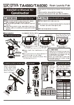
TA4560
Brand: TAKARA Pages: 2

62814
Brand: Lakeland Pages: 12

INGENIO ELEGANCE
Brand: TEFAL Pages: 22

EPICURE
Brand: KitchPRO Pages: 20

LKV168PDBX
Brand: LeCavist Pages: 34

MSG-10
Brand: MPM Pages: 28

QASTB18A01
Brand: Qi Aerista Pages: 20

Black Line 801532
Brand: Magic Home Pages: 6

VFA
Brand: Velux Pages: 16

ASCOLINE 850 MEB 430
Brand: ascobloc Pages: 10


