background image


73 Mall Drive, Commack, NY  11725  •  631-543-2000 (P)  •  631-589-6975 (F) 

www.unitronusa.com  •  [email protected] 
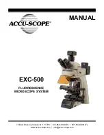
Z12 


STEREO MICROSCOPE 


MANUAL 


Summary of Contents for Z12

Page 1: ...73 Mall Drive Commack NY 11725 631 543 2000 P 631 589 6975 F www unitronusa com info unitronusa com Z12 STEREO MICROSCOPE MANUAL ...

Page 2: ......

Page 3: ...ENTS 4 COMPONENT DIAGRAMS 5 ASSEMBLY DIAGRAM 6 DETAILED ASSEMBLY 7 9 OPERATION ILLUMINATION 10 REFLECTOR 10 FOCUSING TENSION 10 DIOPTER FOCUSING 11 INTERPUPILLARY DISTANCE 11 VIEWING ANGLE 11 CLICK CLICK STOP 12 EYEGUARDS 12 APERTURE DIAPHRAGM 13 LIGHT PATH 13 MOUNTING A MICROSCOPY CAMERA OPTIONAL 13 POLARIZER ANALYZER 14 TROUBLESHOOTING 15 16 MAINTENANCE 17 SERVICE 17 WARRANTY 17 ...

Page 4: ...ope corresponds to your line voltage The use of a different input voltage other than indicated will cause severe damage to the microscope CARE AND MAINTENANCE 1 Do not attempt to disassemble any component including eyepieces objectives or focusing assembly 2 Keep the instrument clean remove dirt and debris regularly Accumulated dirt on metal surfaces should be cleaned with a damp cloth More persis...

Page 5: ...r New York facility Careful quality control procedures ensure each microscope is of the highest quality prior to shipment UNPACKING AND COMPONENTS Your microscope arrived packed in a molded shipping carton Do not discard the carton the carton should be retained for reshipment of your microscope if needed Avoid placing the microscope in dusty surroundings or in high temperature or humid areas as mo...

Page 6: ...OMPONENTS DIAGRAM Trinocular Viewing Head Aperture Diaphragm Control Coarse Fine Focus Adjustment Knobs Eyepiece Stage Insert Plate Camera Photo Port Focus Drive Tension Adjustment Collar Zoom Knob Lock Knob Stage Clip Light Path Selection Slider Objective Base Reflector Adjustment Knob Microscope Body ...

Page 7: ...nd 3mm hex wrenches that are supplied with your microscope when required Be sure to keep this wrench for changing out components or making adjustments When assembling the microscope make sure that all parts are free of dust and dirt and avoid scratching any parts or touching glass surfaces Focus Drive Microscope Body Objective Trinocular Viewing Head Eyepieces Stage Insert Plate Stage Clips Illumi...

Page 8: ...wn in Fig 2 Mounting it improperly will result in the microscope tipping over which may cause damage Mount the Microscope Body Fig 3 Remove the access cap on the side of the focus group and loosen the screw inside with a 3mm hex wrench Carefully slide the microscope body onto the dovetail interface of the focus group as shown Tighten the lock screw on the focus group and replace the access cap Ins...

Page 9: ...bes Lock in the eyepieces by tightening the thumbs screws on each eyepiece tube Mount Unmount the Eyepiece Reticle Fig 7 To mount the reticle unscrew the mounting ring from the eyepiece by turning it counterclockwise Clean the reticle and insert it into the mounting ring with the inscription side as shown Screw the mounting ring back onto the eyepiece To remove the reticle unscrew the mounting rin...

Page 10: ...and slide it in and tighten the lock screw Insert the other end of the illuminator light guide into the socket on the back of the microscope and tighten the lock screw on the top of the socket Insert one end of the power cord on the power supply into the socket on the back of the illuminator Plug the other end into the corresponding socket on the other end of the power supply Plug the other end of...

Page 11: ...to decrease brightness Adjusting the Reflector Fig 12 The reflector has two sides one is a plane mirror the other is sandblasted aluminum Both sides reflect light but the plane mirror is provides a stronger reflection You can change the reflector type or the reflection intensity by rotating the reflector adjustment knob The reflector adjustment knob can also be moved from front to back to achieve ...

Page 12: ...piece to focus the specimen Repeat procedure for the right eyepiece Adjusting Interpupillary Distance Fig 15 To adjust the interpupillary distance hold the left and right eyetubes while observing a specimen Rotate the eyetubes around the central axis until the fields of view of both eyetubes coincide completely A complete circle should be seen in the viewing field when viewing the specimen slide A...

Page 13: ...ise as shown by the arrow in Fig 17 To turn on the Click Stop feature to finely adjust the zoom magnification using a 3mm hex wrench turn the Click Click Stop screw counterclockwise NOTE Be careful not to overturn the screw for either position as it may result in damage to the housing and internal mechanisms of the microscope Adjusting the Eyepiece Eyeguards Fig 18 The eyepieces come standard with...

Page 14: ...es as the default setting at our facilities where the light path selection slider is pushed all the way in Pull the light path selection slider all the way out to send 100 to the top photo port for HDMI digital imaging and documentation Mounting a Microscopy Camera Optional Fig 21 Loosen the lock screw on the camera photo port until it is flush with the inside of the portl remove the dust cap Remo...

Page 15: ...ig 8 p 3 Insert the polarizer with the flat edge closest to the column or aligned with the spring on the inside of the hole in the base and screw it in place using the 3mm hex wrench Replace the stage insert plate Slide the analyzer onto the bottom outside diameter of the objective and tighten the analyzer lock screw With the 360 rotating analyzer you can change the orthogonal state of the polariz...

Page 16: ...is visible in the field of view Dirt dust on the specimen Replace with a clean specimen Dirt dust on the eyepiece Clean the eyepieces The image is not clear Cover glass on the specimen slide Clean the specimen The specimen is not vertical to the objective Adjust it The nosepiece is not in the correct position Turn the nosepiece into the correct position The aperture diaphragm is not open correctly...

Page 17: ...AUSE SOLUTION The lamp doesn t light No power to the lamp Check the power cord is connected correctly The lamp is not installed correctly Install it correctly The lamp burns out Replace the lamp The light intensity is not enough The light intensity control knob is not set properly Adjust the light intensity control knob The wrong lamp is used Replace the lamp with the correct one The lamp keeps bu...

Page 18: ...kmanship for a period of five 5 years for mechanical and optical components and one 1 year for LED bulb and electrical components from the date of invoice to the original end user purchaser This warranty does not cover damage caused in transit misuse neglect abuse or damage resulting from improper servicing or modification by other than UNITRON approved service personnel This warranty does not cov...

Reviews: