background image

GENERAL

Temperature variations are sensed by the liquid
filled bulb which hydraulically transmits motion
through a mechanism which rotates the indicating
pointer and actuates precision snap-acting
switch(es). Controller settings are made by 
turning the adjustment knob(s). Thermometer
types T800 (with enclosure) and T800S 
(skeleton) provide temperature indication only
with no control switches. 

Tools Needed

Screwdriver to secure 

customer supplied screws 

Screwdriver 

5/64” Allen Wrench

INSTALL UNIT WHERE SHOCK, VIBRA-
TION AND TEMPERATURE FLUCTUA-

TIONS ARE MINIMAL. ORIENT UNIT SO THAT
MOISTURE IS PREVENTED FROM ENTERING
THE ENCLOSURE. IT IS IMPERATIVE THAT
PROPERLY RATED EXPLOSION-PROOF SEAL-
ING FITTINGS BE USED FOR ELECTRICAL
WIRE ENTRY OR 820E AND 822E TYPE UNITS.
DO NOT MOUNT UNIT IN AMBIENT TEMPERA-
TURES EXCEEDING PUBLISHED LIMITS.

PREVENTATIVE MAINTENANCE / PERIODIC
TESTING (6 MONTHS OR SOONER AS DIC-

TATED BY THE ENVIRONMENT) IS NECESSARY
TO ENSURE OPERATION OF THE PRODUCT TO
SPECIFICATION. LUBRICATE ALL PIVOT POINTS
AND MOVING PARTS, TO PREVENT CORROSION,
WITH COMPATIBLE DRY LUBRICANTS OR LIGHT
GREASE.

DO NOT KNOCKOUT ANY PLUGS ON
EXPLOSION-PROOF TYPES 820E OR 822E

When mounting 800 or 802 type controls, it may be 
necessary to remove adjustment knob and front cover.
The knob is secured with a 5/64” Allen Setscrew. The
cover is secured by four screws at the corners.

MOUNTING

The controller may be mounted in any position to 
either a surface or panel (1/4” thick maximum).
Locate it where vibration, shock and ambient 
temperature fluctuations are minimal. It is recom-
mended that mounting the unit with the conduit
connection on the top be avoided.
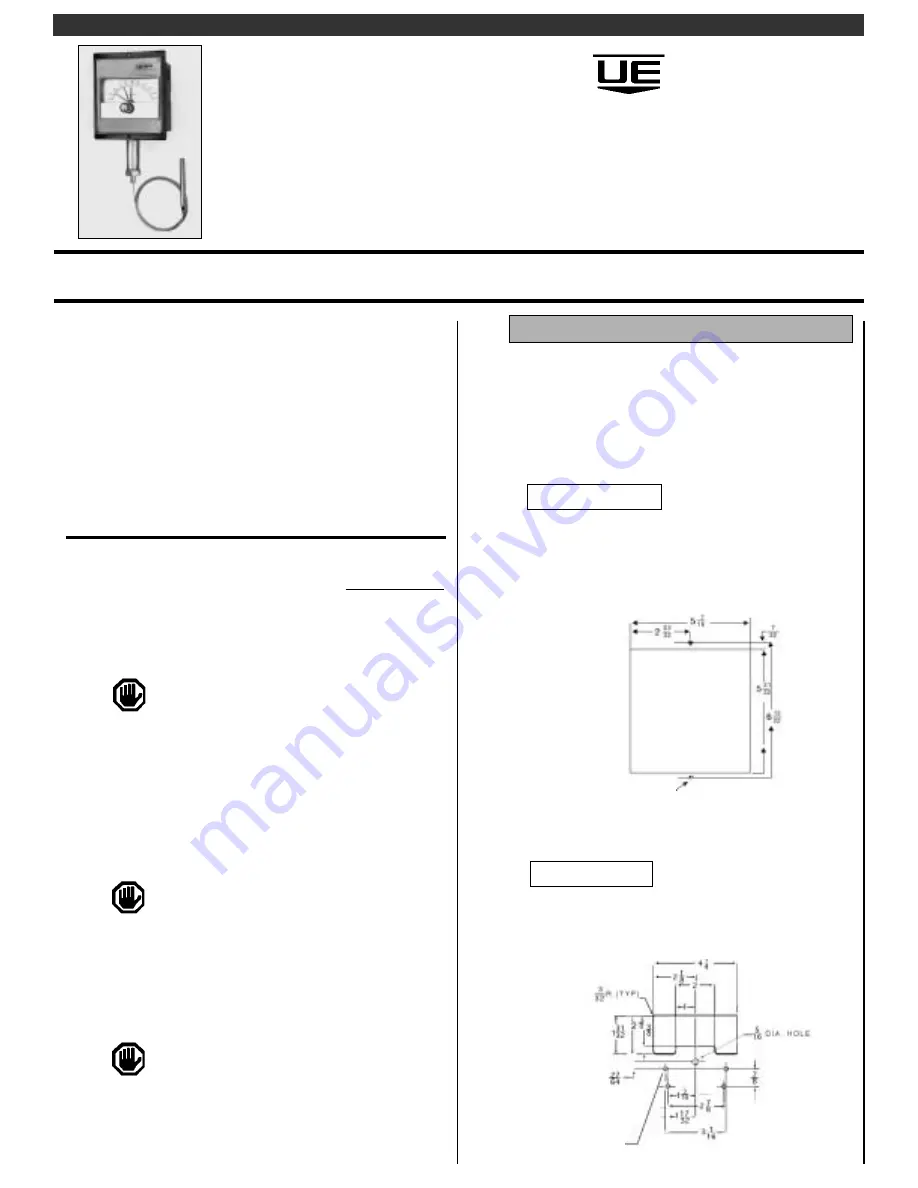
To Flush Mount

(Not applicable to explosion-proof types)  
Cut out the panel as shown in Figure 1A.  Mount
to the panel using the two holes located on the
flange of the enclosure.

To Panel Mount  

(Skeletons) 
Prepare the cut out, drilling the holes for the knob
shaft and the mounting holes per Figure 1B.  

U N I T E D   E L E C T R I C

C O N T R O L S

Installation and Maintenance
Instructions

IM800-03

Please read all instructional literature carefully and thoroughly before starting.  Refer to the final page for the listing of
Recommended Practices, Liabilities and Warranties.

800 Series 
Temperature Controllers and
Thermometers

Types 800, 800S, T800, T800S, 802,
802S, 802P, 802PS, 820E*, 822E*

*Explosion-Proof Class I, Groups B, C, D; 
Class II, Groups E, F & G; Class III

Part I - Installation

Figure 1A - Flush Mounting  

Figure  1B - Panel Mounting (Skeleton)

Clearance for #6 screw 

(4) places (3/16 Max. 

Panel Thickness)

Clearance for #8 screw  - (2) places 

Summary of Contents for 800

Page 1: ...unting 800 or 802 type controls it may be necessary to remove adjustment knob and front cover The knob is secured with a 5 64 Allen Setscrew The cover is secured by four screws at the corners MOUNTING The controller may be mounted in any position to either a surface or panel 1 4 thick maximum Locate it where vibration shock and ambient temperature fluctuations are minimal It is recom mended that m...

Page 2: ... 2B Optional terminal block wiring is available for single or dual switch controls option M100 See Figure 2C To Surface Mount Explosion Proof Types 820E and 822E type units must be surface mounted Drill mounting holes per Figure 1C Option M449 Attach 2 mounting ears found in separate package to recessed areas on back side of enclosure by means of 2 self tapping screws Mount to surface per Figure 1...

Page 3: ...t together within 5 of the dial range Turning the knob positions both switch simultaneously maintain ing a constant separation between switches Replace cover and adjustment knob if removed during installation Controller is ready for operation Turn setting pointer to desired control temperature and start up the process To suit particular process conditions or for greater controller accuracy it may ...

Page 4: ...ct test lights to indicate switch operation or listen for the individual switch clicks Note The adjustment knob slides off adjustment shaft for all controls except the 802 The 802 requires a 5 64 allen wrench Be sure to replace gasket when re assembling In Process Adjustments Use an accurate test thermometer such as a thermocouple with its probe mounted directly to the center of the sensing bulb B...

Page 5: ...itch assembly to pivot post Part III Replacements The set point of switch 1 is determined by the red Adjustment Pointer The set point of switch 2 may be adjusted by up to 25 of the range span below the switch 1 set point by turning adjust ment D in clockwise See Figure 4 The set point of switch 2 should not be above that of switch 1 To align switch 1 to the Adjustment Pointer loosen adjustment A a...

Page 6: ...mounting screws the switch and the insulator 3 Remove leadwires from switch and transfer to new switch 4 Install insulator with new switch and mount in control 5 Install terminal block and adjust temperature setting per PART II Dual Switch Types 1 Remove die cast aluminum cover unscrew and remove terminal block and insulator letting terminal block hang 2 Unscrew terminal block supports and remove ...

Page 7: ...Dimensions 800 Series 820E 822E ...

Page 8: ...s using wire size recommended in installation sheet Use only factory authorized replacement parts and procedures Do not mount unit in ambient temp exceeding published limits For remote mounted temperature units capillary lengths beyond 10 feet can increase chance of error and may require re calibration of set point and indication LIMITED WARRANTY Seller warrants that the product hereby purchased i...

Reviews: