UnionSpecial 60000 D, Instructions For Adjusting
Get the most out of your UnionSpecial 60000 D sewing machine with our comprehensive manual! Offering step-by-step guidance, our free download provides detailed instructions for adjusting and optimizing your machine's performance. Visit manualshive.com to access this invaluable resource and unlock endless possibilities for your sewing projects.
Share
Download


Reviews:
No comments
Related manuals for 60000 D

PIXMA MX882 Series
Brand: Canon Pages: 80

MultiPASS C3500
Brand: Canon Pages: 47

FAX-L280
Brand: Canon Pages: 24

FAX-L280
Brand: Canon Pages: 212

Memory Craft 9450QCP
Brand: Janome Pages: 124

Memory Craft 6300P
Brand: Janome Pages: 69

KC-1200
Brand: ServiceMaster Pages: 12

QK32
Brand: Windsor Pages: 30

PF3200
Brand: GBC Pages: 18

5800 Els
Brand: Gamma Pages: 32

Union Special 36200L220-60
Brand: JUKI Pages: 56
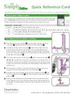
HQ Simply Sixteen
Brand: handi quilter Pages: 2

TH-9701
Brand: DS Produkte Pages: 52

STAIRVILLE AF-X 790 DMX
Brand: thomann Pages: 60

UH9000
Brand: Ching Chi Machine Pages: 22

ETB 1120
Brand: Nacecare Pages: 39

Voice Fax Gateway
Brand: Teltonika Pages: 34

CREWMAN
Brand: BETCO Pages: 24


