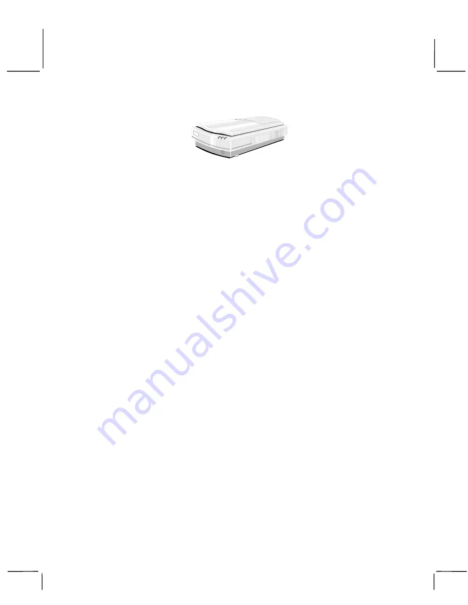
manualshive.com logo in svg
background image

i

PowerLook III

Color Scanner

Operation Manual

Thank you for purchasing the PowerLook III color scanner. With PowerLook III color scanner,
you can easily scan documents and photographs into your computer and maintain them as electronic
copies.

Main Features:

!


High Resolution and Density Range: With a resolution of up to 9600 dpi and high density range, it
produces better gamma transformation, and a more accurate detection of highlight and shadow
details, thereby allowing even distribution of colors.

!


High Scanning Speed, Low Acoustic Noise: The scanner's micro stepping technology greatly increases
scanning speed and at the same time reduces noise level.

!


Intelligent Scanning Control Interface called MagicScan: MagicScan provides a comprehensive range of
scanning control functions. Completing the package are the bundled award-winning and proven
software packages such as buniscan PhotoPerfect.

!


Transparency Adapter: Allows the scanning of films, slides and transparencies up to the full-size
scanning area: 11.4” x 17”.

!


Proprietary Image Noise Reduction: Your scanner uses a sealed optical system design that blocks dust
particles and excess reflections from penetrating the optical unit, thereby overcoming image and
optical noise and ensuring sharp, true-life images.

System Requirements: 486DX or higher (68030 processor or Power Macintosh for Mac users), CD-
ROM drive, hard drive with 20MB free disk space, 4MB memory, Microsoft Windows 3.1 or 95 (Mac
OS 7.0 or later for Mac users), Windows-compatible keyboard, display and mouse. Recommended:
SVGA or higher graphics card.

Part No.: 830639-00

0797_uti

Содержание PowerLook III

Страница 1: ...called MagicScan MagicScan provides a comprehensive range of scanning control functions Completing the package are the bundled award winning and proven software packages such as buniscan PhotoPerfect...

Страница 2: ...demarks of Apple Computer Inc Other trademarks and brand names mentioned in this documentation are trademark properties of their respective holders Copyright 1997 All Rights Reserved No part of this p...

Страница 3: ...th Scan Frames 7 Multiple Scanning Using the A4 35mm Slide Tray 8 Chapter 3 PC Installation 9 Interface Card Installation 9 Connect the Scanner to the Computer 10 Installing the Software 11 How to Sca...

Страница 4: ...Before using your scanner ensure that the carriage lock of scanner is in the unlocked position Insert a coin in the thumbscrew of the optical assembly lock and turn it firmly counterclockwise to unloc...

Страница 5: ...able Connect the SCSI cable to the SCSI interface card and the other end of the SCSI cable to the scanner If your scanner is not chained to other SCSI devices or at the end of the SCSI chain please co...

Страница 6: ...anual is divided into chapters and appendices The chapters give instructions on all aspects of installation troubleshooting and basic scanner maintenance The appendices contain relevant technical info...

Страница 7: ...ealer or the carrier of your package immediately Static Electricity Precautions Static electricity in your body can cause damage to the electronic components on the scanner s printed circuit board or...

Страница 8: ...the object glass Can be raised or lowered to cover a document LED Indicators Three indicators Power Ready and Option Optical Assembly Lock Locks the scanner s optical component system Power Switch Us...

Страница 9: ...important that you lock the optical assembly in place to avoid any possible damage to the scanner s optical components To lock the optical assembly insert a coin and turn it until points to the lock...

Страница 10: ...not used you do not need to change your scanner s SCSI ID number You can directly proceed to hardware connection and software installation For installation instructions proceed to Chapter 2 if you ar...

Страница 11: ...is may cause the liquid to penetrate the seams around the glass and contaminate the mirrors and lenses inside the scanner Spray the liquid on the cleaning cloth then wipe the glass clean Be sure that...

Страница 12: ...the terminator to the remaining SCSI port of your scanner 3 Connect the power cord to the scanner And connect the other end of the power cord to a grounded power socket 4 Turn on the scanner power 5...

Страница 13: ...e Transparency Adapter is fitted before proceeding with the scan 2 Select a Scan Frame size which will hold the original source document without covering up the orientation holes 3 Select the Frame Ho...

Страница 14: ...t glass 3 Line the orientation holes up in such away that the entire tray fits on to the object glass and the slide tray borders line up with the rulers on the scanner s object glass Note Although mis...

Страница 15: ...ting bracket particularly when removing the card from its anti static packaging 1 Turn the computer power off and unplug the power cord 2 Remove the housing cover of the computer Follow the instructio...

Страница 16: ...interface card 2 Connect the other end of the cable to the 50 pin connector of the scanner 3 Connect the power cord to the scanner 4 Turn on the scanner power 5 Turn on the computer power Hardware ins...

Страница 17: ...nsert UMAX MagicScan CD into your CD ROM drive 2 Win95 users click on the Start button on the taskbar and select the Run command Win3 1 users choose the Run command from the File menu of Windows Progr...

Страница 18: ...ure the Transparency Adapter is fitted before proceeding with the scan 2 Select a Scan Frame size which will hold the original source document without covering up the orientation holes 3 Also you must...

Страница 19: ...t glass 3 Line the orientation holes up in such away that the entire tray fits on to the object glass and the slide tray borders line up with the rulers on the scanner s object glass Note Although mis...

Страница 20: ...r the interface card are correct 2 Check the error messages appearing on the screen Does the message point to a hardware problem or software problem If the problem is software related refer to the sof...

Страница 21: ...malfunction or failure occurred Description of what you did to attempt to solve the problem Other observations that may aid the technician in identifying the problem and the solution LED Indicators L...

Страница 22: ...gs whenever scanner operations are attempted This problem is most often caused by another card in the system being set to the same address of your interface card To solve the problem 1 Remove all unne...

Страница 23: ...s Check the SCSI Addresses The illustration below shows the location of the SCSI address selector at the rear panel of the scanner The selector shows the SCSI address setting of the scanner In this ca...

Страница 24: ...rd that does not have another device attached to it In this situation the card will have a built in terminator The card forms one end of the SCSI chain the scanner forms the other end Simply attach th...

Страница 25: ...the scanner 5 Turn on the scanner power 6 Turn on your computer power Installing the Software for PC Users Install software in two easy steps in the following order 1 Image Application Software 2 Magi...

Страница 26: ...pe the appropriate letter in the Run dialog box 4 Follow the on screen instructions to completely install MagicScan Double click the ReadMe icon in the MagicScan group for important up to date informa...

Страница 27: ...canner Settings Scaling 1 to 400 Highlight Shadow 1 255 steps 0 254 steps Contrast Brightness 100 100 Gamma Curve Downloadable Curves 14 bit depth Data Output Color Mode 36 bits hardware 24 bits syste...

Страница 28: ...56 gray levels Halftone Pattern The pattern that is used when varying the ratio of black and white pixels in a halftone image Halftone A 1 bit image file capable of displaying gray levels by varying t...

Страница 29: ...nnected to the same SCSI controller SCSI Device A device that uses the SCSI interface to connect to a computer SCSI ID A unique number between 0 and 7 that identifies each device in a SCSI chain The S...

Отзывы: