Ubiquiti airFiber AF-24, Quick Start Manual
The Ubiquiti airFiber AF-24 is a high-performance 24 GHz point-to-point radio designed for long-range, high-speed wireless connectivity. For detailed setup and configuration instructions, download the free User Manual from manualshive.com. Gain valuable insights on optimizing performance and maximizing range with this essential manual.
Share
Download


Reviews:
No comments
Related manuals for airFiber AF-24
Rino 120
Brand: Garmin Pages: 2
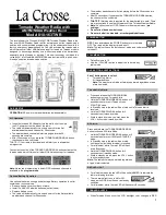
810-1461
Brand: La Crosse Technology Pages: 3
810-106
Brand: La Crosse Technology Pages: 2
810-106
Brand: La Crosse Technology Pages: 4
810-163TWR
Brand: La Crosse Pages: 4
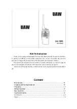
UA-1000
Brand: Nanan Hongda Electronic Pages: 21

BREO/BREW
Brand: Sirius XM RAdio Pages: 26

CR 1140
Brand: camry Pages: 48

DT-210V
Brand: Sangean Pages: 1

CRX060
Brand: Teac Pages: 8

R9921
Brand: Roberts Pages: 28

TOUGH ENOUGH GS350DL
Brand: Grundig Pages: 21

A518
Brand: Retevis Pages: 9

TA-300
Brand: ToooAir Pages: 2

JCR-255
Brand: Jensen Pages: 14

MicroTalk 2
Brand: Cobra Pages: 16

CXT395
Brand: Cobra Pages: 11

LI 6000WXC
Brand: Cobra Pages: 19


