U-Line UHNB315, User Manual & Service Manual
The U-Line UHNB315 comes with a comprehensive User Manual & Service Manual, providing users with detailed instructions and technical support. Easily accessible, our manuals are available for free download at manualshive.com, ensuring a seamless experience and empowering you to fully utilize the product's features and functionalities.
Share
Download


Reviews:
No comments
Related manuals for UHNB315

SB25
Brand: Taylor Pages: 40

Magimix VERTUO NEXT
Brand: Nespresso Pages: 32

Kiaro! 50
Brand: QuickLabel Pages: 136

Black&White 3 CBT
Brand: Thermoplan Pages: 1

Korinto UL 120V
Brand: Necta Pages: 100

the Choc & Cino LMF200
Brand: Breville Pages: 16

s4
Brand: Code Soft Pages: 51
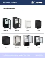
ADA151M
Brand: U-Line Pages: 19

605 E
Brand: Candi Pages: 16

SPB
Brand: Texlabel Pages: 33

XD3-40t Series
Brand: BIXOLON Pages: 2

SPECIAL SELECT FSCM200BM
Brand: Farberware Pages: 12

CDBC
Brand: Bunn Pages: 36

Siena 1/2
Brand: Schaerer Pages: 35

10033478
Brand: Klarstein Pages: 56

NYBAKT STOR BM-50
Brand: Wilfa Smart Pages: 192

Senseo Original HD6554/90
Brand: Philips Pages: 10

Senseo Senseo HD7870/17
Brand: Philips Pages: 11


