


Reviews:
No comments
Related manuals for U-CLR1215SOD-40B
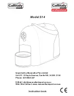
S14
Brand: Caffitaly System Pages: 12

Petra
Brand: Yonanas Pages: 32

Koro Espresso
Brand: Necta Pages: 6

Koro
Brand: Necta Pages: 42

KO1006
Brand: Kolice Pages: 10

Coffee One
Brand: CASO DESIGN Pages: 18

S32R
Brand: Caffitaly System Pages: 64

SMART / S
Brand: Faema Pages: 20

ES 7100
Brand: Wittenborg Pages: 12

CitiZ & milk
Brand: DeLonghi Pages: 18

Esperto Pro
Brand: Tchibo Pages: 112

ONE PRO 2
Brand: Flyte Pages: 20

106115
Brand: Ernesto Pages: 2

CINO XS GRANDE PRO
Brand: Rheavendors Group Pages: 53

414.01
Brand: Capresso Pages: 8

the Barist Express SES875
Brand: Sage Pages: 48

TPC15T
Brand: Curtis Pages: 8

IM2096
Brand: Salton Pages: 8


