


Reviews:
No comments
Related manuals for Marine UMCR015
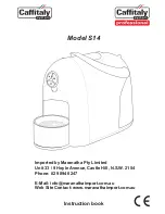
S14
Brand: Caffitaly System Pages: 12

gemini ITALY GEW9P
Brand: GILMAN Pages: 8

ABM4000
Brand: Welbilt Pages: 32

MAGICA
Brand: Bezzera Pages: 80

VG BBA 1
Brand: Venga Pages: 168

DADA VAPOR DOPPIA
Brand: Grimac Pages: 48

XP52 SERIE
Brand: Krups Pages: 126

YT-E-005D
Brand: Moosoo Pages: 8
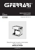
SFOGLIA PROF
Brand: G3 Ferrari Pages: 12

maestria
Brand: MAGIMIX Pages: 54

NT-LP110C
Brand: Netum Pages: 18

F-2000MRH
Brand: Hoshizaki Pages: 33
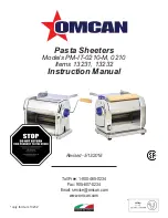
PM-IT-0210-M
Brand: Omcan Pages: 16

681131690690
Brand: GE Pages: 14

D3030-1
Brand: Cornelius Pages: 13

10002520
Brand: Saeco Pages: 48

IG300587
Brand: TEFAL Pages: 63

BVMC-CG12CUP 114202
Brand: Mr. Coffee Pages: 25


