


SEL-0045-001.DOC
REV-0
July 2020
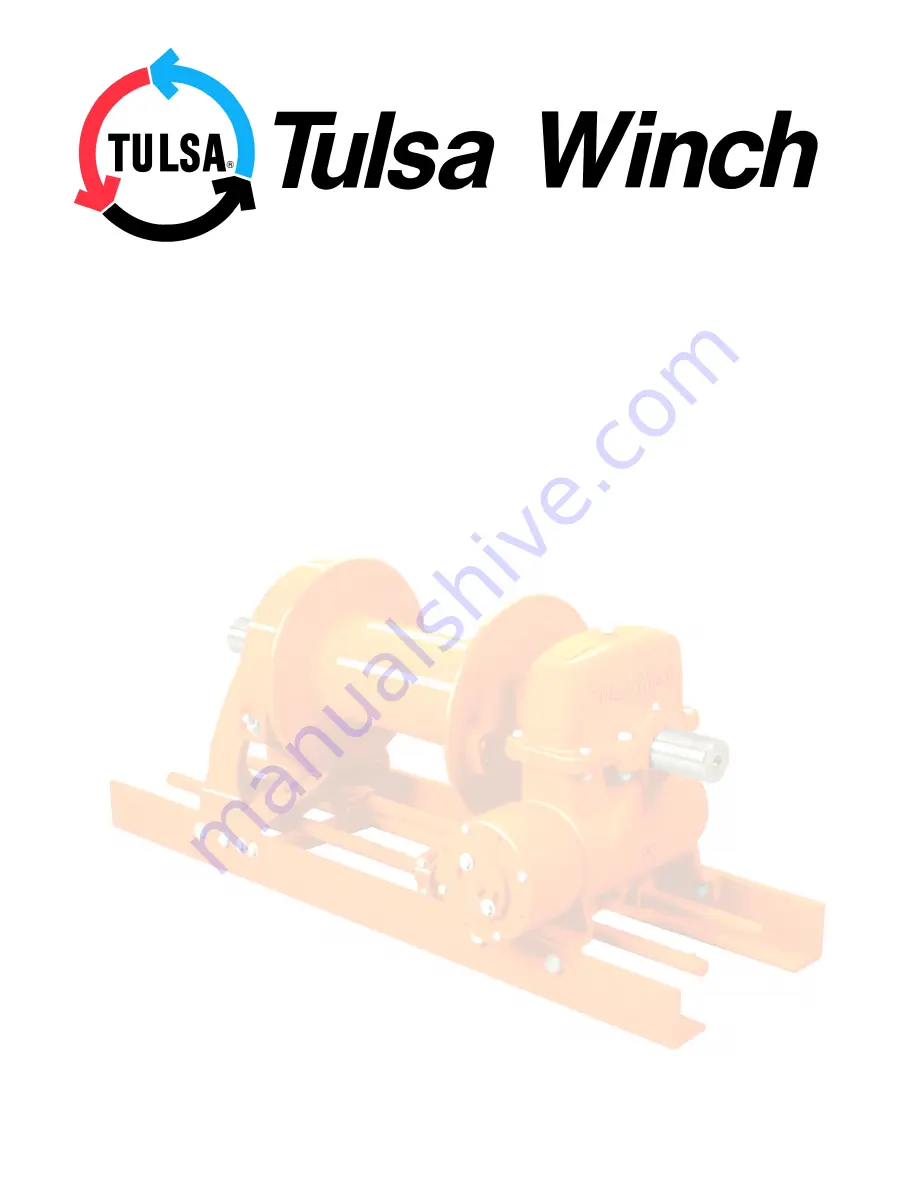
RUFNEK 20
AND
MODEL 23
SERVICE MANUAL
GENERAL INFORMATION .......................................................................................................................... 4
INTRODUCTION AND THEORY OF OPERATION .................................................................................................................4
ASSEMBLY NUMBER EXPLANATION ...................................................................................................................................4
WINCH BREAK-IN ..................................................................................................................................................................4
MODEL CODES ........................................................................................................................................... 5
MAINTENANCE............................................................................................................................................ 6
OIL LEVELS............................................................................................................................................................................7
BRAKE ADJUSTMENT ...........................................................................................................................................................8
DISASSEMBLY ............................................................................................................................................ 9
RUFNEK 20 BRAKE DISASSEMBLY......................................................................................................................................9
MODEL 23 BRAKE DISASSEMBLY........................................................................................................................................10
CLUTCH AND DRUM DISASSEMBLY....................................................................................................................................11
GEARBOX DISASSEMBLY.....................................................................................................................................................12
GEAR INSPECTION INSTRUCTIONS ....................................................................................................................................13
ASSEMBLY ................................................................................................................................................ 14
GEARBOX ASSEMBLY ..........................................................................................................................................................14
MODEL 23 BRAKE ASSEMBLY..............................................................................................................................................15
RUFNEK 20 BRAKE ASSEMBLY............................................................................................................................................15
CLUTCH AND DRUM ASSEMBLY..........................................................................................................................................16
TROUBLESHOOTING................................................................................................................................ 16
BILL OF MATERIAL................................................................................................................................... 16
TORQUE SPECIFICATIONS CHART ........................................................................................................ 16
CLUTCH INSPECTION .............................................................................................................................. 16
ISOMETRIC DRAWING.............................................................................................................................. 16
RUFNEK BRAKE, HYDRAULIC MOTOR, & CLUTCH POSITION INDICATOR...................................... 16
DESIGN SERIES 001


