background image

Hardware Manual

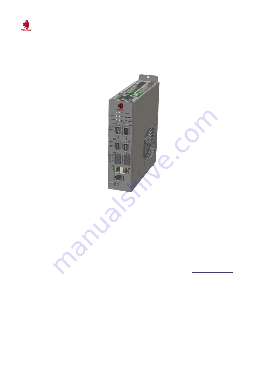
TSD80 / TSD85 / TSD130 Revision 4

Keep all manuals belonging to this product during its life span. Pass all manuals to future owners and

users of this product. This English version is the original version of the product manual.

Document

HWTSD80-TSD130_4_HardwareManual_EP

Version

006

Destination T:\doc\Hardware
Owner

up

Copyright © 2018
Triamec Motion AG

All rights reserved.

Triamec Motion AG
Industriestrasse 49

6300 Zug / Switzerland

Phone

+41 41 747 4040

Email

[email protected]

Web

www.triamec.com

Disclaimer

This document is delivered subject to the following conditions and restrictions:

This document contains proprietary information belonging to Triamec Motion AG. Such information
is supplied solely for the purpose of assisting users of Triamec products.

The text and graphics included in this manual are for the purpose of illustration and reference only.
The specifications on which they are based are subject to change without notice.

Information in this document is subject to change without notice.

2022-01-27

Summary of Contents for TSD130

Page 1: ...rasse 49 6300 Zug Switzerland Phone 41 41 747 4040 Email info triamec com Web www triamec com Disclaimer This document is delivered subject to the following conditions and restrictions This document c...

Page 2: ...ng 12 4 6 Maintenance Cleaning and Repair 13 4 7 Disposal 13 5 Technical description 14 5 1 General features 14 5 2 Electrical Specifications 16 5 2 1 General 16 5 2 2 Rated currents 17 5 2 3 EMC and...

Page 3: ...er without Sin Cos signals 38 7 9 4 Incremental RS422 Encoder with Index 39 7 9 5 Incremental TTL Encoder with Index 40 7 10 Digital inputs and outputs X30 X31 41 7 10 1 Digital inputs 41 7 10 2 Digit...

Page 4: ...al accident prevention regulations 1 2 Standards used Standard Content EN ISO 13849 1 2008 Safety of machinery Safety related parts of control systems IEC 60204 Safety of Machinery Electrical equipmen...

Page 5: ...ed in this manual Each symbol belongs to its danger class with the risk which arises when not complying the safety instruction Symbol Indication DANGER DANGER CAUSED BY HIGH VOLTAGE OR HIGH CURRENT In...

Page 6: ...es after switching off the supply power To be sure measure the voltage of the DC Bus link and wait until the voltage is below 40V CAUTION Only properly qualified personnel are permitted to carry out a...

Page 7: ...rve the chapter 5 5 when you use the safety function STO 2 2 Prohibited use Other use than described in chapter 2 1 is not intended and can lead to injured persons or damage of equipment The use of th...

Page 8: ...ity NOTICE This product can cause high frequency interferences in non industrial environments This can require measures for interference suppression like additional external EMC filters Conformance wi...

Page 9: ...DC bus voltage rating This manual covers 80 and 130 the 80V and 130V products The 80V product is available in 10Arms and 15Arms ver sions the 130V is available in 10Arms only 3 1 1 Fieldbus Variants E...

Page 10: ...ity compensation averages 2 sensors on opposite sides of an encoder disc 3 2 Accessories Triamec Motion AG delivers some useful accessories for the drives The table below shows the most helpful items...

Page 11: ...uch as artificial fabrics and plastic films Place the servo drive on a conductive surface If the packaging is damaged check the unit for visible damage In such an event inform the shipper and the manu...

Page 12: ...Servo drive TSD80or TSD130 Online documentation and setup software TAM System Explorer on CD ROM Mating connectors X1 X2 X3 X4 X30 X31 X40 X41 Table 8 Packaging Accessories must be ordered separately...

Page 13: ...e must be done by the manufacturer Opening the devices means loss of the guarantee Disassemble the equipment as described in chapter 4 5 and send it in the original packaging to Triamec Motion AG 4 7...

Page 14: ...al encoders analog inputs and more 100kHz current controller loop with space vector modulation and an advanced feed forward path 100kHz position controller loop with dual PID architecture and 2 5 filt...

Page 15: ...user program in 10kHz task 1 axis coupling program in 10kHz 1 asynchronous user program Stand alone applications possible PC programming Control Application on Windows PC via TAM SDK for Microsoft NET...

Page 16: ...and Nikon without analog sin cos Digital Inputs 6 Inputs per axis isolated from the logic supply 24V In1 2 300 s In3 6 1200 s Inputs according to IEC EN61131 2 Type 1 with typical currents of 7mA 24V...

Page 17: ...supply is used 5 2 3 EMC and Motor properties There are restrictions on the motor and motor cable properties depending on the PWM frequency In the following table capacity refers to the sum of cable...

Page 18: ...LE FAILURE Be aware that this is not a safety output It is prohibited to use this output alone when failure might cause a dangerous situation 5 4 Dynamic braking During braking with the aid of the mot...

Page 19: ...w STO Active Error TwinCat users Be aware that the system level designer might have chosen to disable direct error event reporting from the triamec module to the user It is at the system level designe...

Page 20: ...e test failure The drive enters the safe error state STO PulseTestFailure If the internal diagnostic circuit temperature is out of range the drive enters the safe error state STO Temperature Limit The...

Page 21: ...ration from the power output If access to the motor power terminals is necessary the servo amplifier must be disconnected from mains supply considering the discharging time of the intermediate circuit...

Page 22: ...Care should be taken not to block the air inlet on the right side of the unit The drive is equipped with temperature monitoring at various positions inside the drive which switches the drive off in c...

Page 23: ...adjacent components Cooling air must be able to flow through the devices without restriction For installation in control cabinets with convection always fit an internal air circulation fan The servo...

Page 24: ...he PCB be low the power stage reaches 70 C Mounting Assemble the servo drives and power supply close together on the conductive grounded mounting plate in the cabinet Mount the drive preferably in ver...

Page 25: ...rom moisture CAUTION Wrong DC Bus voltage unsuitable motor or wrong wiring will damage the amplifier Check the combi nation of servo amplifier and motor Compare the rated voltage and current of the un...

Page 26: ...trol cables separately Connect the protective earth PE to the dedicated screws Wire the STO contacts as discussed in chapter 7 6 Connect the digital inputs and outputs Connect the auxiliary Supply for...

Page 27: ...0 DigIn1 DigIn2 DigIn3 DigIn4 DigIn5 DigIn6 X2 X4 X20 X40 T T X5 X6 PE X1 U V W PE DC STO Ch1 STO Ret STO Ch2 Safe In7 Aux 24V Aux Gnd PE DC Bus DC Bus 24VDC Ground 24VDC Ground Motor AC Mains L1 L2 L...

Page 28: ...Weidm ller BL 3 50 06 180 SN BK BX Order No 1610180000 6 pins 3 5mm pitch 5 5 7 6 X5 X6 In Out Tria Link or EtherCAT RJ 45 connector 7 7 X7 In Out The Ethernet connector can be connected to a TCP IP...

Page 29: ...24VDC logic supply input espe cially the encoder supply and the motor tem perature input The STO supply used to bypass STO is not galvanically isolated from this input Pin Layout X2 Pin Name Descript...

Page 30: ...OTICE Power supply always must be galvanically isolated from the supply mains to comply with isola tion requirements according to EN 61800 5 1 CAUTION Hot plugging of the DC bus link connector is stri...

Page 31: ...3 don t connect currently not available 4 Safe F Output F4 Safe Function Output F4 don t connect currently not available 5 Safe F Output F5 Safe Function Output F5 don t connect currently not availabl...

Page 32: ...ect currently not available 5 Aux 24 V 24V for STO if STO is not used connect to Pin 1 and 3 of X4 6 Aux Gnd Ground for STO if STO is not used connect to Pin 2 of X4 Table 20 Pin out of the Safe Torqu...

Page 33: ...ed a device has a hardware fault EtherCAT This is a fieldbus disclosed in the IEC standard IEC61158 with real time capability It was originally devel oped by Beckhoff Automation and is now managed by...

Page 34: ...th the same specification as the built in encoder 500kHz TOE2 An additional fast encoder input with a cut off frequency of 5MHz TOF2 A pulse train output module TOU1 An analog input sampling module Co...

Page 35: ...ick wire large connection area 360 degree around the cable at the drive side The table below illustrates the use cases of the encoder connection For pulse train options see chapter 7 8 Use case Functi...

Page 36: ...Ground 7 ChA Channel A negative Cosine 1Vpp 8 ChB Channel B negative Sine 1Vpp 9 ChZ Index channel negative RS 422 input 10 n c do not connect 11 EncIn0 TTL Level Input No 0 max 5VDC Input 12 EncIn1...

Page 37: ...C Encoder Supply 2 ChA Channel A positive Cosine 1Vpp 3 ChB Channel B positive Sine 1Vpp 4 DATA Data channel positive RS 422 5 CLOCK Clock channel positive RS 422 6 Gnd Supply Ground 7 ChA Channel A n...

Page 38: ...o not connect 3 n c do not connect 4 DATA Data channel positive RS 422 5 CLOCK Clock channel positive RS 422 not used for Nikon and Tamagawa 6 Gnd Supply Ground 7 n c do not connect 8 n c do not conne...

Page 39: ...ot connect 6 Gnd Encoder Ground 7 ChA Channel A negative RS 422 input 8 ChB Channel B negative RS 422 input 9 ChZ Index channel negative RS 422 input 10 n c do not connect 11 EncIn0 TTL Level Input No...

Page 40: ...n c do not connect 3 n c do not connect 4 ChZ Index channel positive RS 422 input 5 n c do not connect 6 Gnd Encoder Ground 7 n c do not connect 8 n c do not connect 9 ChZ Index channel negative RS 4...

Page 41: ...iled specifications of the input channels Pin Layout X30 X31 Pin Name Description 6 P24Vret 0V ground for digital inputs Internally connected to pins 2 and 4 7 DigIn1 Digital input 1 Logic low 5V Logi...

Page 42: ...r 6 P24V return 30VDC max 1A continuous 2A peak 1s 4 P24Vret 0V ground for digital outputs Internally connected to pins 2 and 6 5 O2 Digital Output 2 High Side Switch Connect your load between this pi...

Page 43: ...NOTICE It is recommended to attach the motor shield directly to the electrical earth of the cabinet 3 Phase AC Motor connection Figure 26 3 phase motor connection Pin Layout X40 X41 Pin Name Descripti...

Page 44: ...e 30 Pin out of the motor connector when connecting a 2 phase AC motor DC Motor connection Figure 28 DC motor connection Pin Layout X40 X41 Pin Name Description Cross Section of Wire Maximum Current 3...

Page 45: ...perature connection Pin Layout X40 X41 Pin Name Description 1 T Positive input 2 T Negative input Table 32 Pin out of the motor temperature connector X40 X41 Information NOTICE The temperature measure...

Page 46: ...ate blinking red The following illustrations show the possible blink sequences and their meaning Blink sequence during start up System Status LED Up to 1 0s 0 4s 0 4s STO Status LED Up to 1 0s 0 4s 0...

Page 47: ...xis 1 LED STO state indications STO Active state is indicated by a short single red blinking of the STO status LED System Status LED STO status LED Axis Status Axis 0 LED Axis Status Axis 1 LED STO fa...

Page 48: ...e in the most effective way please con tact the Customer Support at Triamec Motion AG for assistance Triamec Motion AG Industriestr 49 CH 6300 Zug Switzerland Phone 41 41 747 4040 E mail info triamec...

Page 49: ...9 02 19 mvx ab Commutation frequency limitation TSD80 15 new peak current ratings Di gIn spec 004 12 20 19 mvx New serial encoders adjust power specification 005 12 01 21 dg Guide to mechanical instal...

Reviews: