


92-0756 Rev
. 06081
1
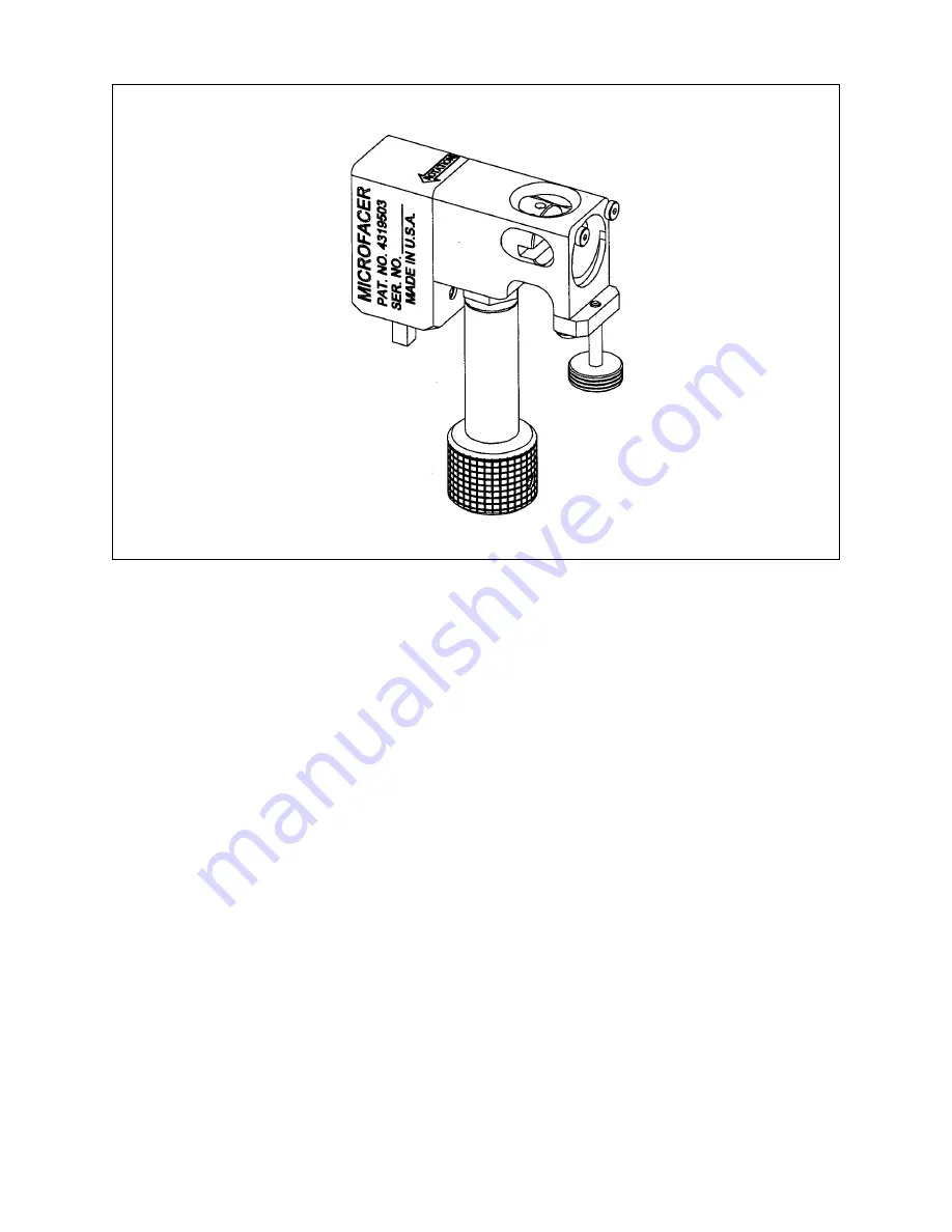
Model 300 MICROF
ACER™
TABLE OF CONTENTS
CUSTOMER MESSAGE
Inside Front Cover
SAFETY PRECAUTIONS
3
SPECIFICATIONS
6
MAINTENANCE
7
OPERATION
8
CUTTING SPEEDS AND FEEDS
10
SADDLE SETS
12
TOOL BITS
15
TROUBLE SHOOTING
16
ACCESSORIES
18
ILLUSTRATED PARTS BREAKDOWN
19
DEWALT SAFETY INSTRUCTIONS
23
TOOL BIT RESHARPENING POLICY
Inside Back Cover
WARRANTY INFORMATION
Inside Back Cover


