


92-1
173 Orig. 040921
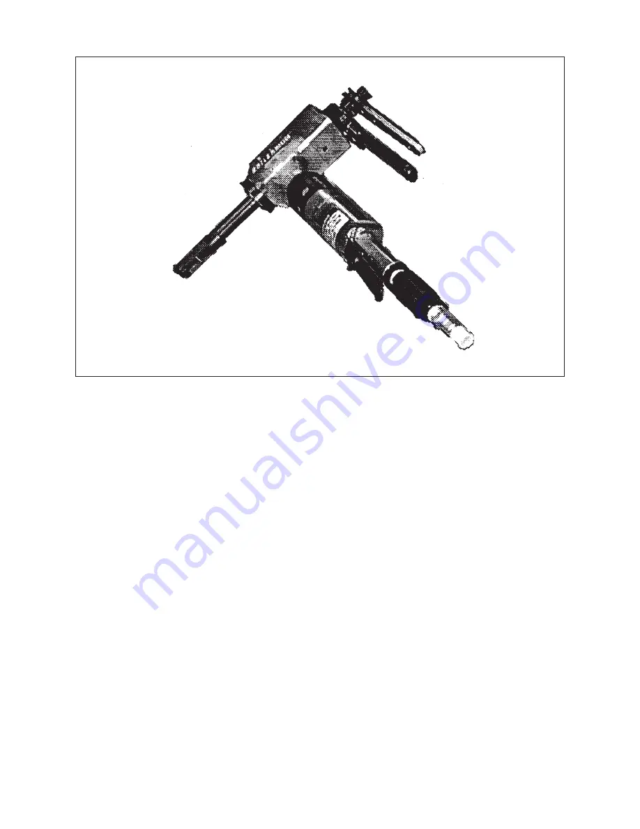
Model BOILERMASTER™
TABLE OF CONTENTS
CUSTOMER MESSAGE
Inside Front Cover
SAFETY PRECAUTIONS
3
GENERAL DESCRIPTION
6
SPECIFICATIONS
7
MAINTENANCE
10
OPERATION
13
CUTTING SPEEDS AND FEEDS
18
JAW BLOCKS, RAMPS AND
20
TOOL BITS
24
TROUBLE SHOOTING
27
ACCESSORIES
29
ILLUSTRATED PARTS BREAKDOWN
30
TOOL BIT RESHARPENING POLICY
Inside Back Cover
WARRANTY INFORMATION
Inside Back Cover


