


TRANSDUCTION
USER’S MANUAL
Ve
rsion 1.0
06
/26/15
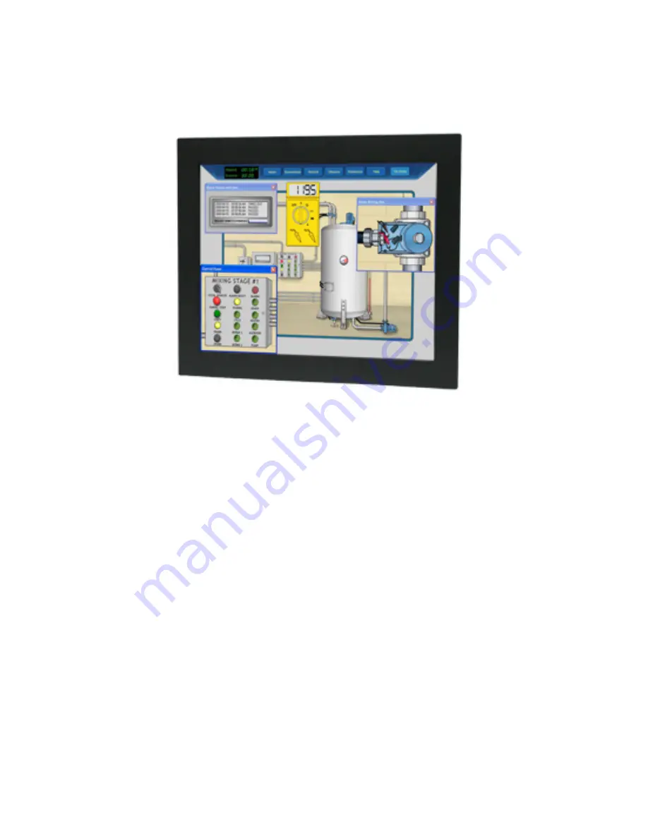
TR-LCD1
9
00-ITX-
7
INDUSTRIAL
PANEL/RACK
MOUNT PC
WITH INTEL DUAL ATOM PROCESSOR
AND 1
9
” LCD TOUCH SCREEN DISPLAY
5155 Spectrum Way, Mississauga, ON, Canada L4W 5A1
TEL: 1-800-268-0427, 905-625-1907
F
AX: 905-625-0531
Email: [email protected]
Summary of Contents for TR-LCD1900-ITX-7
Page 17: ...Jumper Locations on the TR LCD1900 ITX 7 16 TR LCD1900 ITX 7 User Manual ...
Page 22: ...Connector Locations on the TR LCD1900 ITX 7 21 TR LCD1900 ITX 7 User Manual ...
Page 96: ......
Page 97: ......
Page 98: ......
Page 99: ......
Page 100: ......
Page 101: ......
Page 102: ......
Page 103: ......
Page 104: ......
Page 105: ......
Page 106: ......
Page 107: ......


